


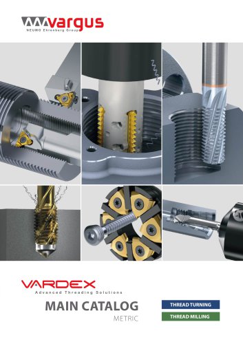
Vardex Thread Milling & Thread Turning Main Catalog

Vardex Thread Milling & Thread Turning Main Catalog
- Advanced Threading Solutions: The catalogue introduces new solid carbide tools and the Helicool family, which includes tools with helical flutes and thru-hole coolant, radial coolant, and combined thread and chamfer capabilities.
- New Products: Highlights include the Multi+ Inserts, Mini-3 IC4.0 TMSD, V6 Inserts, and the MiTM Family, which features a revolutionary 6 cutting corners system and indexable threading inserts for small bores.
- Threading Solutions: The Vardex product line offers a wide range of threading solutions, including thread turning, grooving, and boring tools. The catalogue provides detailed specifications and tooling recommendations for various thread types, including ISO Metric, American UN, and Whitworth threads.
- Software Tools: The TT Gen software assists in selecting the right thread turning tool and cutting conditions, compatible with Windows operating systems.
- Company Profile: Vargus is a leading developer and supplier of precision cutting and deburring tools, with a global presence and a commitment to innovation and quality.
- M Style Toolholders: Feature a 1.5° helix angle. Available in sizes ranging from 5/8” to 50mm.
- T Style Toolholders: Have a 0° helix angle. Sizes range from 1/2” to 40mm.
- FQ and CQ Spare Parts: Include specifications for off-set and drop head-qualified toolholders, with a 1.5° helix angle.
- Miniature Toolholders: Designed for precision industries, available in square and round shank styles with a 0.5° helix angle.
- Standard Spare Parts: Include insert screws, anvil screws, and Torx keys for various toolholder sizes.
- V6 Style Spare Parts: Specially designed for V6 inserts, requiring specific toolholders without an anvil.
- U Style and Z+ Style Spare Parts: Feature dual system options (screw or clamp) and are available with a 1.5° helix angle.
- Thread Turning Kits: Include external, internal, and combined kits with multiple inserts and Torx keys.
- Insert Kits: Offer a variety of external and internal inserts, including V6 options.
- Toolholders with coolant channels are available as standard.
- Carbide shank toolholders are recommended for high accuracy and specific bar length to diameter ratios.
- Specific toolholders are designed for right-hand (RH) inserts, with options for left-hand (LH) inserts by modifying the ordering code.
The document provides detailed specifications for internal toolholders, highlighting a 2.5˚ helix angle. It mentions that left-handed tools are available upon request and that the toolholders are made with carbide shanks and implants.
Mini-L Spare Parts
Specifications for Mini-L spare parts include insert size, ordering codes, dimensions, and anti-vibration systems. The document lists various models with specific dimensions and features such as carbide implantation.
Micro Toolholders
Details on micro toolholders include double-ended and single-ended spare parts, with specifications on insert diameter, shank diameter, and clamping systems. The document emphasizes a simple clamping system using a large screw for securing inserts.
Thread Turning Technical Data
This section covers thread terminology, machining multi-start threads, insert profile styles, and thread turning methods. It explains the differences between radial and flank infeed methods and provides guidance on calculating the helix angle and choosing the right anvil.
Thread Terminology
Definitions and explanations of various thread-related terms such as internal and external threads, lead, pitch, and helix angle are provided. The document also describes different thread profiles and their applications.
Thread Turning Methods
Various methods for thread turning are outlined, including right-hand and left-hand external and internal threads. The document provides diagrams and descriptions for each method.
Calculating the Helix Angle
Instructions on calculating the helix angle are provided, along with a diagram to assist in understanding the process. The document emphasizes the importance of using the correct helix angle to prevent rubbing on the workpiece.
Anvils and Anvil Kits
Information on anvils includes ordering codes and resultant helix angles. The document advises using specific anvils with corresponding inserts to ensure proper thread turning.
Additional Information
The document includes tables and diagrams to support the technical data, providing a comprehensive guide for selecting and using toolholders and inserts in thread turning applications.
- Thread Type: 5”x6 ACME Internal Right Hand
- Material: Stainless Steel Austenitic
- Bore Diameter: 5”
- Pitch: 6 tpi
- Cutting Speed: 140 m/min
- Number of Passes: 18
- Helix Angle: -0.65°
1. Choose the Thread Turning Method: Reverse helix method is used.
2. Choose the Insert Size: 4IL6ACME VTX
3. Choose the Toolholder: AVR 40-4LH
4. Determine the Helix Angle: -0.65° for a pitch of 6 tpi and bore diameter of 127mm.
5. Choose the Correct Anvil: YE4-2N
- Use a left hand toolholder for right hand thread turning.
- Feed direction should be away from the chuck to facilitate chip removal.
- Use a coated carbide grade for increased flank wear.
- Increase coolant flow rate for insufficient cooling.
- Increased flank wear: Reduce cutting speed, use coated insert, increase depth of cut per pass, use a coated carbide grade, increase coolant flow rate.
- Uneven cutting edge wear: Choose the correct anvil, use the alternating flank infeed method.
- Extreme plastic deformation: Reduce depth of cut, increase cooling, reduce cutting speed, use suitable carbide grade.
- Nose Radius Issues: If the nose radius is too small, it is recommended to decrease the depth of cut, increase the number of passes, enhance coolant flow rate, reduce cutting speed, use a tougher carbide, or use an insert with a larger radius.
- Cutting Edge Breakage: Caused by large depth of cut, extreme plastic deformation, insufficient cooling, unsuitable carbide grade, or instability. Solutions include decreasing depth of cut, using tougher carbide, increasing coolant flow, and checking system stability.
- Built-up Edge: Addressed by changing cutting speed and using a coated carbide.
- Thread Profile Issues: If the thread profile is too shallow, adjust tool height, measure workpiece diameter, or change the cutting edge sooner.
- Poor Surface Quality: Can be improved by increasing cutting speed, choosing the correct anvil, or using alternate flank or radial infeed methods.
- Ordering Code System: The document provides a detailed ordering code system for grooving inserts, including specifications for external and internal retaining ring grooves, thread undercuts, and face grooves.
- Insert Specifications: Includes details on insert size, style, type, groove standard, groove depth, and carbide grade.
- DIN Standards: The document references various DIN standards for retaining ring grooves and thread undercuts, specifying dimensions and profiles for different applications.
- Micro and Mini Inserts: Specifications for micro and mini inserts are provided, including dimensions and minimum bore diameters.
- Tables provide detailed dimensions for different insert sizes and profiles, including groove standard dimensions, anvil holders, and minimum bore diameters.
This document provides detailed specifications and ordering information for various thread milling toolholders, including Twin Flute Offset Toolholder (TMO), Standard Single Point TM Toolholder (TMS), Vertical Insert TM Toolholder (TMV), and TM Shell Mill. It also includes spare parts for VARDEX TM and TMSH toolholders.
Specifications and Ordering Codes
The document lists various toolholders with their respective insert sizes, ordering codes, and dimensions. It provides detailed measurements such as length (L), diameter (D), and insert screw specifications. Sample orders are provided for clarity.
Technical Data on Thread Milling
The technical section explains the thread milling process, which requires a milling machine with three-axis control capable of helical interpolation. It describes the helical motion and the different approaches for initiating thread production, including Tangential Arc Approach, Radial Approach, and Tangential Line Approach.
Approach Methods
- Tangential Arc Approach: Recommended for high-quality threads, involves smooth tool entry and exit.
- Radial Approach: Simpler method, may leave small marks and cause vibration in hard materials.
- Tangential Line Approach: Simple and effective for external threads.
Preparation and Calculations
The document provides formulas for calculating rotational velocity and feed rates at the cutting edge and tool center line. It emphasizes the importance of these calculations for effective CNC programming.
Grades and Applications
Different grades are recommended for various materials, such as VBX for steel and cast iron, VTX for stainless steel, and VK2 for cast iron and nonferrous metals.
CNC Programming Codes
A list of "G" codes for CNC programming is provided, detailing commands for positioning, interpolation, and tool compensation.
Conclusion
This document serves as a comprehensive guide for selecting and using thread milling toolholders, providing essential technical data and programming instructions for optimal performance.
- Helical Flutes - External and Internal: This section lists tools for external and internal threading with specifications such as thread pitch, ordering codes, dimensions (D, D2, L, Le), number of flutes (Z), and teeth (Zt). It covers both ISO Metric and American UN standards.
- Deep Threading: Focuses on long tools designed for deep holes, providing specifications for ISO Metric threads. It includes parameters like thread pitch, dimensions, and bore diameter.
- Miniature Thread Mills (MilliPro): Details miniature thread mills for both 2x and 3x thread diameters, covering ISO Metric and American UN standards. It includes thread pitch, ordering codes, dimensions, and bore diameter.
- ISO Metric Helical Flutes: Defined by R262 (DIN 13) with a tolerance class of 6g/6H.
- American UN Helical Flutes: Defined by ANSI B1.1.74 with a tolerance class of 2A/2B.
- BSP and BSPT Helical Flutes: Defined by B.S.2779:1956 and B.S.21:1985 with medium and standard BSPT tolerance classes.
- NPT and NPTF Helical Flutes: Defined by USAS B2.1:1968 and ANSI 1.20.3-1976 with standard NPT and NPTF tolerance classes.
The document provides detailed specifications for various thread milling tools, including dimensions, number of flutes, and ordering codes. It covers both NPTF and Pg thread types, with specific details on thread pitch, external/internal diameters, and lengths. The tools are available with either 3 or 5 flutes, and the ordering code must be adjusted accordingly.
Standards and Tolerances:
The document references ANSI 1.20.3-1976 and DIN 40430 standards for thread definitions and tolerance classes, ensuring compatibility and precision in manufacturing processes.
Material Grades and Coatings:
Several grades are mentioned, including VTH, VTS, and VTN, each with specific applications. VTH is a general-purpose grade with TiAlN coating for wear resistance, while VTN is uncoated and suitable for aluminum. VTS is TiAlN coated, ideal for cast iron.
Cutting Speeds and Feeds:
The document provides comprehensive tables for cutting speeds (Vc) and feed rates (f) for various materials, categorized by hardness and type (e.g., steel, stainless steel, cast iron, non-ferrous metals). Recommendations are given for different tool grades and material conditions (e.g., annealed, hardened).
Groove Milling:
Details on groove milling inserts and toolholders are provided, including dimensions, insert styles, and ordering codes. The document specifies groove standards like DIN 471/472 and BS 4518, with static and dynamic groove types.
Recommendations:
For optimal performance, the document suggests setting the feed rate at tool entry to 70% lower than the threading feed. This ensures smoother tool entry and reduces wear.
Applications:
The tools and specifications are applicable across various industries requiring precision threading and milling, including automotive, aerospace, and general manufacturing.
1. Carbon Steel: Carbon content ranges from 0.55% to 0.85%.
2. Low Alloy Steel: Alloying elements ≤5%, with both non-hardened and hardened options.
3. High Alloy Steel: Alloying elements >5%, available in annealed and hardened forms.
4. Cast Steel: Includes low and high alloy options.
5. Stainless Steel: Covers ferritic, austenitic, and cast variants, with non-hardened and hardened states.
6. Cast Iron: Includes malleable and grey cast iron, with variations in tensile strength.
7. Non-Ferrous Metals: Focus on aluminium and copper alloys, with distinctions between wrought and cast forms.
8. Heat Resistant Materials: High temperature alloys and titanium alloys, with specifications for annealed and aged states.
9. Hardened Materials: Extra hard steel with specific hardness ratings.
- Rotational Velocity (N): Calculated using the formula N = (1000 x Vc) / (π x D).
- Cutting Speed (Vc): Derived from the formula Vc = (N x π x D) / 1000.
- Toolholder Cutting Diameter (D2): Specific to the tool being used.
- Tool Feed Rate (F1): Measured at the cutting edge.
- Feed per Tooth per Rotation (f): Important for determining peripheral feed.
- The document provides guidance on the application of various grades, emphasizing the versatility of the VKX grade for general use.
- TiN coated tools are highlighted for their effectiveness.
- The document lists contact details for Vargus distributors worldwide, including China, Denmark, France, Germany, India, Israel, Poland, Switzerland, the UK, and the USA.
- Mention of TT GEN and TM GEN software for thread turning and milling, available for download from the Vargus website.
Catalog excerpts

Turning and Milling Tools Main Catalogue Threading Grooving Boring Advanced Threading Solutions METRIC
Open the catalog to page 1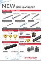
NEW SOLID CARBIDE TOOLS HELICOOL FAMILY MILLIPRO FAMILY DEEP THREADING HELICAL NEWIN THIS CATALOGUE MULTI+ INSERTS MINI-3 IC4.0 TMSD V6 INSERTS MICROSCOPE MiTM FAMILY ..Helicool Helical Flutes with Thru-Hole Coolant ..Helicool-R (HCR) Radial Coolant ..Helicool-C (HCC) Thread & Chamfer in One Tool ..Thriller (HTC) Drill, Thread & Chamfer in One Tool ..A Revolutionary 6 Cutting Corners System ..Indexable Threading Insert for Small Bores ..Multi-Flute Indexable Thread Milling for Fast Machining ..New Advanced Clamping System for Micro Single Ended Tools ..Improved Design for Multi-Tooth Inserts...
Open the catalog to page 2
N U M B E R O N E I N T H R E A D I N G VARGUS is a world leading developer, manufacturer and supplier of high-quality, precision cutting and deburring tools. The company’s VARDEX product line is the number one source for threading solutions worldwide and includes the largest range of thread turning and thread milling solutions as well as an extensive range of solutions for micro-machining. Established in 1960, VARGUS is a member of the NEUMO Ehrenberg Group, a diversified multi-national organization headquartered in Knittlingen, Germany. With a network of international distributors, warehouses...
Open the catalog to page 4
VA R D E X S P E C I A L TOOLS Tailor Made VARDEX engineers and toolmakers have the know-how and experience to design special cutting tools tailored to customer requirements. Whether it’s a special, complex shape or a non-standard size, our Special Tools service can quickly produce the tool you need using the latest techniques and technology. For specific details, contact your nearest VARDEX sales representative. .. VARDEX expertise .. Fast quotation .. Competitive delivery
Open the catalog to page 5
> Threading > Grooving > Boring Turning
Open the catalog to page 7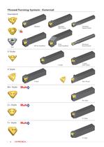
6 Thread Turning System - External Standard U Style V Style M+ Style Z+ Style T+ Style Standard Off-Set Qualified SCB Standard With Clamp Drop Head-Qualified Standard Square Shank Miniature Round Shank U Style with Clamp Slim Throat M+ Style Z+ Style T+ Style V Style U Style
Open the catalog to page 8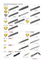
7 Thread Turning System - Internal Standard U Style V Style Z+ Style Mini-3 M+ Style T+ Style Mini-L Micro SCB Standard API Standard With Clamp Carbide Shank Miniature Square Shank Miniature Round Shank U Style U Style with Clamp M+ Style T+ Style Mini-3 Mini-L Micro Single-Ended Micro Double-Ended Mini-L Adjustable Mini-3 Adjustable Z+ Style V Style
Open the catalog to page 9
Thread Turning > Inserts
Open the catalog to page 19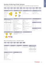
19 Thread Turning Inserts 3 1 2 E 3 R 4 1.5 5 ISO 6 7 8 9 10 VTX 11 12 1- Insert Size 5L - IC5.0L mm 4.0K - IC4.0 mm 6.0 - IC6.0 mm 2 - IC1/4” 3 - IC 3/8” 4 - IC 1/2” 5 - IC5/8” 2 - Insert Style 3 - Type of Insert E - External I - Internal EI - External +Internal 4 - RH/LH Insert R - Right Hand Insert L - Left Hand Insert None - Right + Left Insert 7 - No. of Cutting Corners 6C - V6 Cutting Corners None - All Others 9 - No. of Teeth (for multitooth Style) 2, 3, 5, 6, 8 10 - Multi tooth Style 11 - Carbide Grade VKX, VTX, VCB, VM7, VK2, VK2P, VKP, VHX, VBX 12 - Coarse Pitch Inserts 158/... 8 -...
Open the catalog to page 21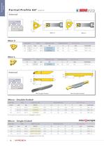
22 Thread Turning Inserts Mini-3 Insert Size Pitch Ordering Code Dimensions mm Min. Bore dia. IC L mm mm tpi RH r Y F mm Toolholder 4.0 6 0.5-1.25 48-20 4.0KIRA60... 0.05 0.6 3.7 6.35 .NVR.5-4.0K 6.0 10 0.5-1.5 48-16 6.0IRA60... 0.05 0.9 5.3 10.00 .NVR 1..-6.0 Mini-L Insert Size Pitch Ordering Code Dimensions mm Min Bore dia. IC mm tpi RH r Y F mm Toolholder 5.0L 0.5-1.5 48-16 5LIRA60... 0.05 0.9 4.65 8.0 .NVR 10.-5L Micro - Double Ended Insert dia. Pitch Ordering Code Dimensions mm Min. Bore dia. d mm mm tpi RH/LH r L1 L F Y mm Toolholder 3.0 0.5-1.0 48-24 3.0SIRF60... 0.05 16 50 1.46 0.9 3.3...
Open the catalog to page 24
25 Thread Turning Inserts Mini-3 Insert Size Pitch Ordering Code Dimensions mm Min Bore dia. IC L mm mm tpi RH r Y F mm Toolholder 4.0 6 0.5-1.25 48-20 4.0KIRA55... 0.05 0.6 3.8 6.45 .NVR.5-4.0K 6.0 10 0.5-1.50 48-16 6.0IRA55... 0.05 0.9 5.3 10.00 .NVR 1..-6.0 Mini-L Insert Size Pitch Ordering Code Dimensions mm Min. Bore dia. IC mm tpi RH r Y F mm Toolholder 5.0L 0.5-1.5 48-16 5LIRA55... 0.05 0.9 4.65 8.0 .NVR 10.-5L Micro - Double Ended Insert dia. Pitch Ordering Code Dimensions mm Min. Bore dia. d mm mm tpi RH/LH r L1 L F Y mm Toolholder 3.0 0.5-1.0 48-24 3.0SIRF55... 0.05 16 50 1.46 0.9 3.3...
Open the catalog to page 27
32 Thread Turning Inserts M+ Style Insert Size Pitch Teeth Ordering Code Dimensions mm Anvil IC L mm mm RH h min X Y RH Toolholder 3/8” 16 1.0 3 3IR1.0ISO3M+... 0.58 1.7 2.6 1.5 2 3IR1.5ISO2M+... 0.87 1.6 2.4 YI3M AVR..-3 2.0 2 3IR2.0ISO2M+... 1.15 2.0 3.1 1/2” 22 1.5 3 4IR1.5ISO3M+... 0.87 2.5 3.8 2.0 2 4IR2.0ISO2M+... 1.15 2.0 3.1 YI4M AVR..-4 2.0 3 4IR2.0ISO3M+... 1.15 3.2 5.1 5/8” 27 3.0 2 5IR3.0ISO2M+... 1.73 3.0 4.7 YI5M AVR..-5M V Style Insert Size Pitch Ordering Code Dimensions mm IC L mm mm RH LH h min X Y T Toolholder 5/8”V 27 6.0 5VIR6.0ISO... 5VIL6.0ISO... 3.46 1.0 3.3 6 8.0 5VIR8.0ISO......
Open the catalog to page 34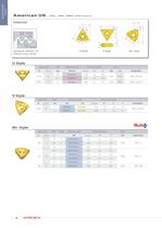
42 Thread Turning Inserts U Style Insert Size Pitch Ordering Code Dimensions mm Anvil IC L mm tpi RH+LH h min X Y RH LH Toolholder 1/2”U 22 4.5 4UI4.5UN... 3.26 2.4 11.0 YI4U YE4U AVR..-4U (LH) 4 4UI4UN... 3.67 2.4 11.0 5/8”U 27 3 5UI3UN... 4.89 2.7 13.7 YI5U YE5U AVR..-5U (LH) V Style Insert Size Pitch Ordering Code Dimensions mm IC L mm tpi RH LH h min X Y T Toolholder 5/8”V 27 4 5VIR4UN... 5VIL4UN... 3.67 1.0 3.3 6 NVR..-5V (LH) 3 5VIR3UN... 5VIL3UN... 4.89 1.0 4.3 8 M+ Style Insert Size Pitch Teeth Ordering Code Dimensions mm Anvil IC L mm tpi RH h min X Y RH Toolholder 3/8” 16 12 2 3IR12UN2M+......
Open the catalog to page 44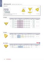
50 Thread Turning Inserts IC L Y X L X Y IC R 0.137P h 55° R 0.137P L X Y T IC V Style Insert Size Pitch Ordering Code Dimensions mm IC L mm tpi RH LH h min X Y T Toolholder 5/8”V 27 4 5VIR4W... 5VIL4W... 4.07 1.0 3.3 6 3 5VIR3W... 5VIL3W... 5.42 1.0 4.3 8 NVR..-5V (LH) 2.5 5VIR2.5W... 5VIL2.5W... 6.51 1.0 5.2 10 M+ Style Insert Size Pitch Teeth Ordering Code Dimensions mm Anvil IC L mm tpi RH h min X Y RH Toolholder 3/8” 16 14 2 3IR14W2M+... 1.16 2.0 3.0 YI3M AVR..-3 1/2” 22 11 2 4IR11W2M+... 1.48 2.3 3.5 YI4M AVR..-4 U Style Insert Size Pitch Ordering Code Dimensions mm Anvil IC L mm tpi RH+LH...
Open the catalog to page 52All Vargus catalogs and technical brochures
 GROOVEX Main Catalog
220 Pages
 VARDEX Main Catalog
532 Pages
 V-Mill and V-Drill
88 Pages
 Vargus Focus
8 Pages
Archived catalogs
 VARDEX Mini-3 IC 5.0
12 Pages
 The Touch Finishing
20 Pages
 RedLine Thick Thread Turning Inserts
16 Pages
 VARDEX Mega Line
20 Pages
 VARDEX Industrial Solutions
20 Pages
 Spotlight 2011-2012
6 Pages
 Spotlight 2010 - NEW Products
6 Pages
 RedLine Thread Turning Inserts
8 Pages
 Thread Milling Handbook
30 Pages
 VARGUS Threading Products
4 Pages


- Milling tool
- Solid milling cutter
- Drilling tool
- Steel milling cutter
- Solid drill bit
- Metal milling cutter
- Clamping milling cutter
- Milling cutter with cylindrical shank
- Grade
- End mill
- Cast iron milling cutter
- Solid carbide milling cutter
- Ball nose milling cutter
- Multi-purpose drilling tool
- Coated milling cutter
- High-performance milling cutter
- Tungsten carbide drill bit
- Milling chuck
- Machining tool holder