
Catalog excerpts

Voltage and frequency protection relay
Open the catalog to page 1
Trace back information: Workspace Main version a10
Open the catalog to page 2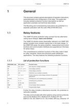
This document contains general descriptions of operation instructions, parameterization and configuration of the relay. This guide also includes detailed protection function descriptions as well as application examples and technical data sheets. The Mounting and Commissioning Instructions are published in a separate publication with the code VRELAY/EN MC/xxxx. The VAMP 50 series protection relay concept has two alternative casing layout designs: basic and slimline. The VAMP 50 slimline series (hereinafter referred to as VAMP 50S series) includes more compact casing than in the basic design....
Open the catalog to page 7
and DNP 3.0. An optional communication option is required for this (see Chapter 15 Order information). The relay can be controlled in three ways: Locally with the push-buttons on the relay front panel Locally using a PC connected to the USB port on the front • Via remote control over the optional remote control port on the relay rear panel. HAZARD OF ELECTRIC SHOCK, EXPLOSION, OR ARC A live current transformer secondary circuit must not be opened without turning off the primary side of the transformer and short circuiting transformer secondary circuits first Failure to follow these...
Open the catalog to page 8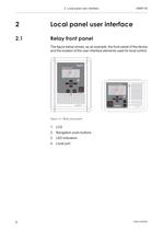
2 Local panel user interface Local panel user interface Relay front panel The figure below shows, as an example, the front panel of the device and the location of the user interface elements used for local control.
Open the catalog to page 9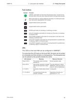
2 Local panel user interface 2.1 Relay front panel CANCEL push-button for returning to the previous menu. To return to the first menu item in the main menu, press the button for at least three seconds. INFO push-button for viewing additional information, for entering the pass- word view and for adjusting the LCD contrast. programmable function push-button. programmable function push-button. ENTER push-button for activating or confirming a function. arrow UP navigation push-button for moving up in the menu or increasing arrow DOWN navigation push-button for moving down in the menu or de-...
Open the catalog to page 10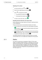
2.1 Relay front panel 2 Local panel user interface 2- Enter the four-digit password and push Push ■ and adjust the contrast. To increase the contrast, push I To decrease the contrast, push To return to the main menu, push Resetting latched indicators and output relays All the indicators and output relays can be given a latching function There are several ways to reset latched indicators and relays: From the alarm list, move back to the initial display by pushing for approx. 3s. Then reset the latched indicators and output • Acknowledge each event in the alarm list one by one by pushing C3...
Open the catalog to page 11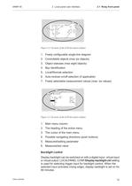
VAMP 55 2 Local panel user interface 2.1 Relay front panel Figure 2.2: Sections of the LCD dot matrix display 1. Freely configurable single-line diagram 2. Controllable objects (max six objects) 3. Object statuses (max eight objects) 4. Bay identification 5. Local/Remote selection 6. Auto-reclose on/off selection (if applicable) 7. Freely selectable measurement values (max. six values) Figure 2.3: Sections of the LCD dot matrix display 1. Main menu column 2. The heading of the active menu 3. The cursor of the main menu 4. Possible navigating directions (push buttons) 5. Measured/setting...
Open the catalog to page 12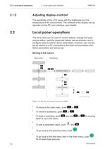
2.2 Local panel operations 2 Local panel user interface 2.1.2 Adjusting display contrast The readability of the LCD varies with the brightness and the temperature of the environment. The contrast of the display can be adjusted via the PC user interface, see chapter. Local panel operations The front panel can be used to control objects, change the local/ remote status, read the measured values, set parameters, and to configure relay functions. Some parameters, however, can only be set by means of a PC connected to the local communication port. Some parameters are factory-set. Main menu To...
Open the catalog to page 13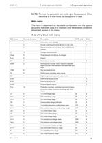
2 Local panel user interface 2.2 Local panel operations NOTE: To enter the parameter edit mode, give the password. When the value is in edit mode, its background is dark. Main menu The menu is dependent on the user's configuration and the options according the order code. For example only the enabled protection stages will appear in the menu. A list of the local main menu
Open the catalog to page 14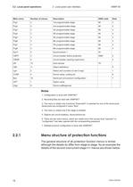
2.2 Local panel operations 2 Local panel user interface 1. Configuration is done with VAMPSET 2. Recording files are read with VAMPSET 3. The menu is visible only if protocol "ExternallO" is selected for one of the serial ports. Serial ports are configured in menu "Bus". 4. The menu is visible only if the stage is enabled. 5. Objects are circuit breakers, disconnectors etc. 6. There are two extra menus, which are visible only if the access level "operator" or "configurator" has been opened with the corresponding password. 7. Detailed protocol configuration is done with VAMPSET. 2.2.1 Menu...
Open the catalog to page 15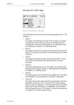
VAMP 55 2 Local panel user interface 2.2 Local panel operations First menu of I>> 50/51 stage first menu I>> STATUS ExDO Prot I> I>> Iv> I > Status SCntr TCntr SetGrp SGrpDI Force 50 / 51 5 2 1 OFF Figure 2.5: First menu of I>> 50/51 stage This is the status, start and trip counter and setting group menu. The content is: • • SCntr 5 The stage has picked-up a fault five times since the last reset or restart. This value can be cleared if the operating level is at least “Operator”. • TCntr 2 The stage has tripped two times since the last reset or restart. This value can be cleared if the...
Open the catalog to page 16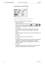
2.2 Local panel operations 2 Local panel user interface VAMP 55 Second menu of I>> 50/51 stage second menu Stage ExDI ExDO Prot I>> CBWE OBJ I>> SET 50 / 51 setting group 1 ILmax 403A Status I>> 1013A I>> 2.50xIn 0.60s t>> Figure 2.6: Second menu(next on the right) of I>> 50/51 stage This is the main setting menu. The content is: • Stage setting group 1 These are the group 1 setting values. The other setting group can be seen by pressing push buttons and then or . Setting groups are explained in Chapter 2.2.2 Setting groups. • • Status – Status of the stage. This is just a copy of the...
Open the catalog to page 17All Vamp catalogs and technical brochures
-
vamp 265
2 Pages
-
VAMP 11V
16 Pages
-
VAMP 1 1 F
16 Pages
-
VAMP 50 series
20 Pages
-
VAMP 96 and VAMP 260
12 Pages
-
VAMP 57
16 Pages
-
VAMP 259
12 Pages
-
VAMP 230, VAMP 255 and VAMP 257
16 Pages
-
VAMP 125
1 Pages
-
VAMP 125 Unit for flexible
12 Pages
-
VAMP 120 & 121
8 Pages
-
VAMP 11V
16 Pages
-
VAMP 321
12 Pages
-
VAMP 59
12 Pages
-
VAMP 120
8 Pages
-
VAMP 40
24 Pages
-
VAMP 50
20 Pages
-
VAMP 230
16 Pages
-
VAMP 210
2 Pages
-
VAMP 135
8 Pages
Archived catalogs
-
VAMP 221_2013
16 Pages
-
VAMP 221_2011
16 Pages
-
VAMP 96
16 Pages
-
ARC Protection
20 Pages
-
Customer
28 Pages
-
Vamp Arc Protection Series
16 Pages
-
Vamp Feeder/Motor Manager
16 Pages
-
Selection table
1 Pages
-
Vamp Protection Relays
16 Pages


