

VAMP 265M motor differential protection relay

VAMP 265M motor differential protection relay
The VAMP 265M is a motor differential protection relay offering comprehensive protection functions. It includes instructions for parameterization, configuration, and setting adjustments.
Supports protection functions like overcurrent, undercurrent, differential overcurrent, and more. It includes a disturbance recorder and supports communication protocols such as Modbus, Profibus, and IEC standards.
Features a local panel with a display, keypad, and indicators. Users can navigate menus, adjust settings, and access logs. Configuration options include setting parameters and configuring digital inputs/outputs.
Offers various protection functions with specific features and settings, including inverse time operation and programmable stages.
Includes event logging, disturbance recording, current transformer supervision, and system clock synchronization.
Covers accuracy, harmonics, RMS values, demand values, and scaling options for current measurements.
Involves output relays, digital inputs, virtual inputs/outputs, and logic functions. Users can configure output and blocking matrices.
Supports various communication ports and protocols for integration with other systems and remote monitoring.
Includes examples like restricted earth fault protection and differential protection using the VAMP 265M.
Details on connections, auxiliary voltage, communication connectors, and optional modules. Covers protection functions, tests, and environmental conditions.
Includes abbreviations, construction details, order information, and revision history.
Highlights risks of electric shock, explosion, or arc flash if safety instructions are not followed.
Allows control of objects, status changes, value readings, and parameter settings. Features setting groups, fault logs, and operating levels.
Manages functions like manual triggering, status checks, and recording settings.
Configurable for relay status, forced control, and output signal configuration.
Allows resetting counters, reading protection status, and defining interlockings.
Includes device setup, language selection, and clock synchronization.
Details communication protocols for various ports.
Managed using VAMPSET software.
Allows on-site parameterization, software loading, and continuous monitoring.
Provides differential protection for motors and generators, suitable for industry, power plants, and offshore applications.
Includes digital signal handling, high measuring accuracy, and customizable functions.
Employs numerical technology with digital processing for signal filtering and protection functions.
Supports multiple protection stages, each independently configurable.
Includes setting groups, forcing start or trip conditions, and blocking mechanisms.
Prevents too frequent starts of asynchronous motors.
Includes two stages with bias current calculation and dual slope characteristics.
Emphasizes flexibility, configurability, and robust protection capabilities.
Outlines parameters for temperature rise, measured current, and overload settings.
Used to block other stages by measuring harmonic ratios.
Used in transformer over-excitation scenarios.
Includes circuit breaker failure protection, arc fault protection, and programmable stages.
Describes inverse time operation and recorded values for protection stages.
Outlines event logging processes and disturbance recorder functions.
Monitors wiring between relay terminals and CTs.
Monitors circuit breaker wear and estimates wear based on permissible cycles.
Includes event buffer size, disturbance recorder channels, and CT supervision settings.
Details procedures for detecting faults and monitoring circuit breaker conditions.
Describes internal clock usage and synchronization methods.
Calculates total active time of selected digital inputs or outputs.
Includes settable timers for programmable logic or control settings.
Collects faults and fault currents from all enabled overcurrent stages.
Describes self-supervision functions of the microcontroller.
Includes RMS values, demand values, and scaling for measurement values.
Describes output relays, digital inputs, virtual inputs/outputs, and logic functions.
Outlines timeout settings for object control.
Describes control signals and settings for objects.
Describes mode selection for output relays.
Supports programmable logic for boolean signals.
Includes standard communication ports and optional Ethernet port.
Details protocols for data transfer and communication settings.
Describes various communication protocols and their functions.
Protects a zone against earth faults with specific CT requirements.
Provides calculations for stabilizing resistance and voltage limitation.
Outlines CT classification and accuracy requirements.
Provides safety factors and formulas for CT power determination.
Details differential protection settings and calculations.
Explains the importance and procedures for trip circuit supervision.
Outlines specifications for trip circuit supervision using digital inputs.
Provides equations for power calculation and resistor values.
Includes recommendations for resistor usage and configurations.
Describes connections on the rear panel of the relay.
Specifies auxiliary voltage and optional module polarity.
Details pin assignments for communication connectors.
Includes figures and tables for configurations and connections.
Provides specifications for retardation, inaccuracy, and protection stages.
Describes disturbance recorder and order information.
Includes nominal current and supply voltage options.
Lists firmware updates and enhancements.
Provides contact details for Schneider Electric.
Catalog excerpts

Motor differential protection relay User manual
Open the catalog to page 1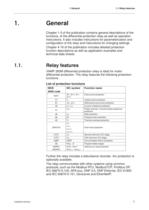
1 General 1. 1.1 Relay features General Chapter 1-3 of the publication contains general descriptions of the functions, of the differential protection relay as well as operation instructions. It also includes instructions for parameterization and configuration of the relay and instructions for changing settings. Chapter 4-16 of the publication includes detailed protection function descriptions as well as application examples and technical data sheets. 1.1. Relay features VAMP 265M differential protection relay is ideal for motor differential protection. The relay features the following protection...
Open the catalog to page 7
1.2 User interface 1.2. 1 General User interface The relay can be controlled in three ways: Locally with the push-buttons on the relay front panel Locally using a PC connected to the serial port on the front panel or on the rear panel of the relay (both cannot be used simultaneously) Via remote control over the remote control port on the relay rear panel. 1.3. Operating Safety HAZARD OF ELECTRIC SHOCK, EXPLOSION, OR ARC FLASH A live current transformer secondary circuit must not be opened without turning off the primary side of the transformer and short circuiting transformer secondary circuits...
Open the catalog to page 8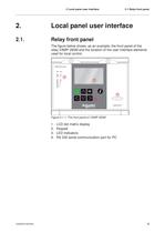
2 Local panel user interface 2.1 Relay front panel 2. Local panel user interface 2.1. Relay front panel The figure below shows, as an example, the front panel of the relay VAMP 265M and the location of the user interface elements used for local control. Figure 2.1-1. The front panel of VAMP 265M 1. 2. 3. 4. V265M/EN M/A004 LCD dot matrix display Keypad LED indicators RS 232 serial communication port for PC 9
Open the catalog to page 9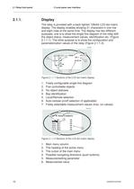
2.1 Relay front panel 2.1.1. 2 Local panel user interface Display The relay is provided with a back lighted 128x64 LCD dot matrix display. The display enables showing 21 characters in one row and eight rows at the same time. The display has two different purposes: one is to show the single line diagram of the relay with the object status, measurement values, identification etc. (Figure 2.1.1-1). The other purpose is to show the configuration and parameterization values of the relay (Figure 2.1.1-2). Figure 2.1.1-1 Sections of the LCD dot matrix display 1. 2. 3. 4. 5. 6. 7. Freely configurable...
Open the catalog to page 10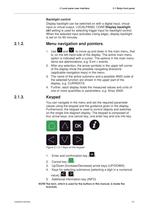
2 Local panel user interface 2.1 Relay front panel Backlight control Display backlight can be switched on with a digital input, virtual input or virtual output. LOCALPANEL CONF/Display backlight ctrl setting is used for selecting trigger input for backlight control. When the selected input activates (rising edge), display backlight is set on for 60 minutes. 2.1.2. Menu navigation and pointers 1. Use and to move up and down in the main menu, that is, on the left-hand side of the display. The active main menu option is indicated with a cursor. The options in the main menu items are abbreviations,...
Open the catalog to page 11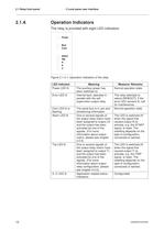
2.1 Relay front panel 2.1.4. 2 Local panel user interface Operation Indicators The relay is provided with eight LED indicators: Figure 2.1.4-1. Operation indicators of the relay LED indicator Power LED lit Error LED lit Com LED lit or flashing Alarm LED lit Trip LED lit A- C LED lit 12 Meaning The auxiliary power has been switched on Internal fault, operates in parallel with the self supervision output relay The serial bus is in use and transferring information One or several signals of the output relay matrix have been assigned to output LA and the output has been activated by one of the signals....
Open the catalog to page 12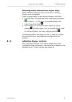
2 Local panel user interface 2.1 Relay front panel Resetting latched indicators and output relays All the indicators and output relays can be given a latching function in the configuration. There are several ways to reset latched indicators and relays: From the alarm list, move back to the initial display by pushing for approx. 3 s. Then reset the latched indicators and output relays by pushing . Acknowledge each event in the alarm list one by one by pushing equivalent times. Then, in the initial display, reset the latched indicators and output relays by pushing . The latched indicators and relays...
Open the catalog to page 13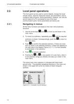
2.2 Local panel operations 2.2. 2 Local panel user interface Local panel operations The front panel can be used to control objects, change the local/ remote status, read the measured values, set parameters, and to configure relay functions. Some parameters, however, can only be set by means of a PC connected to one of the local communication ports. Some parameters are factory-set. 2.2.1. Navigating in menus All the menu functions are based on the main menu/submenu structure: 1. Use the arrow keys main menu. and to move up and down in the 2. To move to a submenu, repeatedly push until the required...
Open the catalog to page 14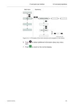
2 Local panel user interface 2.2 Local panel operations Figure 2.2.1-2 Principles of the menu structure and navigation in the menus 6. Push item. 7. Push V265M/EN M/A004 to obtain additional information about any menu to revert to the normal display. 15
Open the catalog to page 15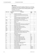
2.2 Local panel operations 2 Local panel user interface Main menu The general menu structure is shown in Figure 2.2.1-2. The menu is dependent on the user‘s configuration and the options according the order code. For example only the enabled protection stages will appear in the menu. A list of the local main menu Main menu Number of menus 1 5 1 Meas Imax Month 9 21 Evnt DR Runh 2 2 2 TIMR DI DO ExtAI ExDI ExDO Prot 6 5 4 3 3 3 8 Mstat N> ΔI> ΔI>> I> I>> I‘> I‘>> Ist> I< I2> I2>> 1 4 7 5 5 3 5 3 3 3 3 3 I‘2> T> Io> Io>> Io>>> 16 13 3 3 5 3 3 Description Interactive mimic display Double size measurements...
Open the catalog to page 16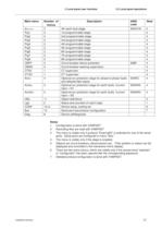
2 Local panel user interface Main menu Io>>>> Prg1 Prg2 Prg3 Prg4 Prg5 Prg6 Prg7 Prg8 CBFP CBWE CTSV CT‘SV ArcI> Number of menus 3 3 3 3 3 3 3 3 3 3 4 1 1 4 ArcIo> 3 ArcIo2> 3 OBJ Lgic CONF Bus Diag 11 2 10+2 13 6 2.2 Local panel operations Description 4th earth fault stage 1st programmable stage 2nd programmable stage 3rd programmable stage 4th programmable stage 5th programmable stage 6th programmable stage 7th programmable stage 8th programmable stage Circuit breaker failure protection Circuit breaker wearing supervision CT supervisor CT‘ supervisor Optional arc protection stage for phase-to-phase...
Open the catalog to page 17All Vamp catalogs and technical brochures
 VAMP 321
12 Pages
 VAMP 120 & 121
8 Pages
 VAMP 57
16 Pages
 vamp 265
2 Pages
 VAMP 11V
16 Pages
 VAMP 1 1 F
16 Pages
 VAMP 50 series
20 Pages
 VAMP 96 and VAMP 260
12 Pages
 VAMP 259
12 Pages
 VAMP 230, VAMP 255 and VAMP 257
16 Pages
 VAMP 125
1 Page
 VAMP 125 Unit for flexible
12 Pages
 VAMP 11V
16 Pages
 VAMP 59
12 Pages
 VAMP 55
190 Pages
 VAMP 120
8 Pages
 VAMP 40
24 Pages
 VAMP 50
20 Pages
 VAMP 230
16 Pages
 VAMP 210
2 Pages
 VAMP 135
8 Pages
Archived catalogs
 VAMP 221_2013
16 Pages
 VAMP 221_2011
16 Pages
 VAMP 96
16 Pages
 ARC Protection
20 Pages
 Customer
28 Pages
 Vamp Arc Protection Series
16 Pages
 Vamp Feeder/Motor Manager
16 Pages
 Selection table
1 Page
 Vamp Protection Relays
16 Pages

- Digital I/O
- Windows software
- IO module
- Digital IO module
- Fieldbus I/O module
- Optical cable
- Programming software
- Optical data cable
- Serial converter
- Current protection relay
- Digital protection relay
- Voltage protection relay
- Interface module
- PLC software
- Electric motor protection relay
- Programmable protection relay
- Panel-mount protection relay
- Earth-leakage protection relay
- Over-current protection relay