SERIES-EL-930-ELECTRIC-ACTUATOR
1 /4Pages

SERIES-EL-930-ELECTRIC-ACTUATOR
1 /4Pages
Catalog excerpts

SERIES EL-930 SPRING RETURN ELECTRIC ACTUATORS A SPRING RETURN electric actuator designed tor load requirements up to 450'lbs. The actuator comes standard with two auxiliary switches (Form C>, an internal low power heater, a NEMA 4X environmental rating, and in 120/230VAC or 24VAC/DC supply voltages. The EL Series mechanical connections utilize an IS05211 mounting system, size F07 with an 8 point 17mm female drive. The EL Series is offered in three different control modes ...On/Off (2 position control), Jog (floating control) and Proportional (modulating control). Application requirements will dictate whether to utilize a CW (clockwise spring return) or CCW (counter-clockwise spring return) model. While power is present, the actuator will respond to drive control signals depending on the model chosen. A 2 position unit will drive until it reaches the full end of travel setting opposite the spring return direction. A Jog unit will drive OPEN, CLOSED or HOLD position until it receives a command to move otherwise. A Proportional control unit will follow an analog control signal for positioning and will HOLD until a modified control signal is received. In each of these models a motor brake unit is utilized to HOLD the actuator in position until commanded to move OR a loss of supply voltage. If power is lost or removed at any time, the brake is released and the mechanical spring mechanism returns the actuator to it's normal (unloaded) position. Once the spring mechanism has been released, the actuator will not drive under power again until a) the unit has reached it's fail stop (unloaded) position, and b) power has been restored to the actuator. While the actuator is in it's fail stop position, the MANUAL HANDLE may be employed to position the actuator anywhere between the UNLOADED and LOADED position, and the actuator will HOLD in that position indefinitely, regardless of whether power is present. The MANUAL HANDLE must return the actuator to its fully UNLOADED position BEFORE electrical operation of the actuator will be possible, THIS IS A SAFFTY FFATURF Additionally, if the actuator has been driven electrically to its fully LOADED position, the MANUAL HANDLE cannot be used to drive the actuator back to its fully UNLOADED position. THIS IS ALSO A SAFETY FEATURE. This prevents unexpected release of stored spring energy. Remote indication of actuator status is possible by utilizing built-in auxiliary switches. These dry contacts can show when an actuator has been overridden after power has been restored, indicating the actuator will NOT operate under control again until it has been manually returned to the full Fail-Safe position (explained above).
Open the catalog to page 1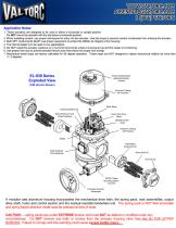
Application Notes: 1. These actuators are designed to be used in either a horizontal or upright position. Do NOT mount the actuator with the top below a horizontal position. 2. When installing conduit, use proper techniques lor entry into the actuator. Use drip loops to prevent conduit condensate Irom entering the actuator. 3. Both NPT conduit ports MUST use proper equipment to protect the NEMA 4x integrity of the housing. 4. The internal heater is to be used in ALL applications. 5. Do NOT install the actuator outdoors or in humid environments unless it is powered up and the heater is functioning....
Open the catalog to page 2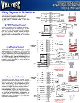
Wiring Diagrams for EL-900 Series Field Control Device may be relay contact Switch type. Pilot device 10A MAX. Auxiliary switches dry type Form C Terminals accept 12-18ga solid/ stranded wire. OrVOff or 2 Position control is used for damper or valve applications where the requirement is for either fully open or fully closed positioning. This actuator must drive to it's end of travel opposite the spring fail position. Loss of control signal or power before reaching it's end of travel will cause the unit to spring SHOWN WITH Jog/Floating Control Jog/Floating control is used for damper or valve...
Open the catalog to page 3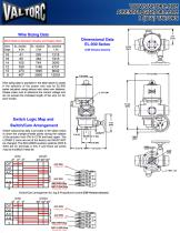
Wire Sizing Data
Open the catalog to page 4All Valtorc catalogs and technical brochures
 545SN series
2 Pages
 535SN series
2 Pages
 SANITARY BUTTERFLY VALVE
2 Pages
 Series CS/SS 2000
4 Pages
 Solenoid Valve
4 Pages
 BALL-VALVE-SERIES-190
1 Page
 BALL-VALVE-SERIES-200
1 Page
 BALL-VALVE-SERIES-210
1 Page
 BALL-VALVE-SERIES-220
1 Page
 BALL VALVE SERIES 230
1 Page
 ball-valve-series-110
1 Page
 ball-valve-series-100
1 Page
 awwa butterfly valve
5 Pages
 Ball valve
1 Page
 SERIES-IP6000
4 Pages
 UPS-SERIES9
1 Page
 VP-700-POSITIONER
5 Pages
 ACTUATED VALVE PACKAGE
4 Pages
 ACTUATION
4 Pages
 BALL VALVE
4 Pages
 BUTTERFLY VALVE
4 Pages
 FIRE SAFE FUSIBLE LINK VALVE
4 Pages
 KNIFE GATE
4 Pages
 POULTRY
1 Page
 SANITARY VALVE
4 Pages
 V BALL - V PORT
4 Pages
 310 series
10 Pages
 460 series
2 Pages
 390 series
4 Pages
 FS-30
FS-304 Pages
 FS10 series
1 Page
 LSN7 series
6 Pages
 LSN4-SS
1 Page
 Limit Switch LSN4
2 Pages
 9AAG-GOLD
1 Page
 VP V-Port Valve
4 Pages
 Series PV 600 Plug Valves
3 Pages
 VP-900 Positioner
3 Pages
 VP-700 Positioner
5 Pages
 Solenoid Valve 9AAG
2 Pages
 Limit Switch LSN7
6 Pages
 quarter turn valve actuator
4 Pages
 ups9-series
1 Page
 900 series
2 Pages
 800 series
2 Pages
 EL700V
15 Pages
 gate globe valve
15 Pages
 pvc valve
4 Pages
 solenoid valve
10 Pages
 PVC strainer
1 Page
 flanged gate valve
1 Page
 gate valve
1 Page
 control ball valve
6 Pages
 check valve
1 Page
 safety-relief valve
5 Pages
 control-valve
4 Pages
 sanitary-check-540-sn
2 Pages
 600 series
3 Pages
 300 series
10 Pages
 100 series
1 Page
 pneumatic actuator
4 Pages
 EL 750
5 Pages
 EL600
EL6006 Pages


