EL700V
1 /15Pages

EL700V
1 /15Pages
Catalog excerpts

SERIES EL-700-V ELECTRIC ACTUATORS_ 1. ^ No manual operation of the actuator while the device is energized. 2. The actuator is equipped with an over heating protection device. When the motor exceeds the temperature of 257" F (125°C), the overheat protection device will automatically switch 3. It is necessary to take additional leakage protection steps when installing the actuator and putting it into service. 4. Be sure to double check the input voltages and all other connections. 5. Do not wire two or more actuators in either series or parallel. Otherwise, it can cause movement to become out...
Open the catalog to page 2
S (SHUT) Direction of arrow (clockwise) represents close. O (OPEN) Direction of arrow (counter-clockwise) represents open.
Open the catalog to page 3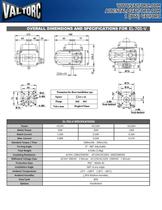
OVERALL DIMENSIONS AND SPECIFICATIONS FOR EL-705-V
Open the catalog to page 4
SPECIFICATIONS FOR MODULATING ACTUATORS
Open the catalog to page 8
CONTROL CIRCUIT WIRING The opening and closing operation of the actuator is regulated with the travel limit switches which open the power circuit to the motor. Two power legs and a common are needed in order to drive the actuator open and closed. Auxiliary switches are for status of valve (open/closed). 24VAC, EL-700-V and EL-700-V-M units are not equipped with the manual override push ON/OFF button. In order to operate the 24VAC and EL-700-V units with the manual override, power must be turned off to unit. All other units are equipped with the manual override push ON/OFF button which cuts off...
Open the catalog to page 9
APPLICATION REQUIREMENTS Installation Conditions • Series EL-700-V Units can be installed outdoors and indoors - NEMA 4X or IP67. • Series EL-700-V Units are not explosion proof and caution should be taken to avoid inflammable and explosive environments. • Installation consideration should be taken into account to allow for manual operation of the units as • Ambient temperature should be within -30°C - 60°C. Medium Working Temperature • Care should be taken to prevent the heat of the working medium from exceeding the actuator ambient temperature limits. • When the temperature of the working medium...
Open the catalog to page 10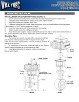
INSTALLATION OF ACTUATOR TO VALVE (FIG. 3) 1. Rotate valve to full closed position. Ensure that the valve rotates freely with no obstruction. 2. Using the proper bolts attach the bracket to the valve - tighten loosely. 3. Place the coupling onto the stem of the valve 4. Using the manual override handle, rotate the actuator to the full closed position so that the pointer indicator points to "SHUT" (stating position of the scale). 5. Insert the output drive shaft of the actuator into the coupling. 6. Attach bracket to actuator and tighten all bolts. 7. Drive the actuator using the manual crank...
Open the catalog to page 11
ADJUSTMENT OF ACTUATOR - 2 POSITION Units are calibrated at the factory to rotate 90" - if any adjustment is needed please use the following procedure. 1. Adjustment of electric limits for 2 position valves (Fig 5.) a. Full Closed position adjustment: Using the manual hand wheel or hand crank, drive the valve to the full closed position. Ensure the pointer on the dome lid is pointing red zero "shut". If not, remove lid and loosen dome indicator and re-position to red zero "shut". To adjust the closed limit switch, loosen shut position regulating shaft (S) using 2mm Allen wrench and rotate the...
Open the catalog to page 12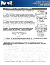
ADJUSTMENT OF ACTUATOR - MODULATING 1. Following procedures in section "INSTALLATION OF ACTUATOR TO VALVE" install the actuator onto the valve and ensure proper movement of unit by utiliz- ing the manual crank handle. 2. Drive the valve to the full closed position using the manual crank handle and ensure that the mechanical stops are not making contact with the housing or« screws. If there is contact, back off the mechanical limit screws until there is no contact. Loosen the lock screw on the dome indicator and position the scale to the ^J'^J full closed position "0" (SHUT POSITION) - tighten...
Open the catalog to page 13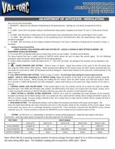
ADJUSTMENT OF ACTUATOR - MODULATING does not have this functionality. • DB SWITCH - Allows for the selection of dead band on the potentiometer. Settings are 1-10 which correspond to 0,5% to • LI LAMP - Green LED is the power indicator and illuminates when power is applied to terminals "N" and "L" of the Servo- Control • L2 LAMP - Red LEO shows a malfunction of the control signal input and illuminates when the control signal is lost or weak. • L3 LAMP - Red LED shows a malfunction of the positioning circuit and illuminates when the potentiometer lead is open, • L4 LAMP - Red LED shows an over-torque...
Open the catalog to page 14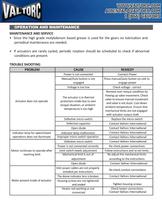
• Since the high grade molybdenum based grease is used for the gears no lubrication and periodical maintenance are needed. • If actuators are rarely cycled, periodic rotation should be scheduled to check if abnormal TROUBLE SHOOTING
Open the catalog to page 15All Valtorc catalogs and technical brochures
 545SN series
2 Pages
 535SN series
2 Pages
 SANITARY BUTTERFLY VALVE
2 Pages
 Series CS/SS 2000
4 Pages
 Solenoid Valve
4 Pages
 BALL-VALVE-SERIES-190
1 Page
 BALL-VALVE-SERIES-200
1 Page
 BALL-VALVE-SERIES-210
1 Page
 BALL-VALVE-SERIES-220
1 Page
 BALL VALVE SERIES 230
1 Page
 ball-valve-series-110
1 Page
 ball-valve-series-100
1 Page
 awwa butterfly valve
5 Pages
 Ball valve
1 Page
 SERIES-IP6000
4 Pages
 UPS-SERIES9
1 Page
 VP-700-POSITIONER
5 Pages
 ACTUATED VALVE PACKAGE
4 Pages
 ACTUATION
4 Pages
 BALL VALVE
4 Pages
 BUTTERFLY VALVE
4 Pages
 FIRE SAFE FUSIBLE LINK VALVE
4 Pages
 KNIFE GATE
4 Pages
 POULTRY
1 Page
 SANITARY VALVE
4 Pages
 V BALL - V PORT
4 Pages
 310 series
10 Pages
 460 series
2 Pages
 390 series
4 Pages
 FS-30
FS-304 Pages
 FS10 series
1 Page
 LSN7 series
6 Pages
 LSN4-SS
1 Page
 Limit Switch LSN4
2 Pages
 9AAG-GOLD
1 Page
 VP V-Port Valve
4 Pages
 Series PV 600 Plug Valves
3 Pages
 VP-900 Positioner
3 Pages
 VP-700 Positioner
5 Pages
 Solenoid Valve 9AAG
2 Pages
 Limit Switch LSN7
6 Pages
 quarter turn valve actuator
4 Pages
 ups9-series
1 Page
 900 series
2 Pages
 800 series
2 Pages
 gate globe valve
15 Pages
 pvc valve
4 Pages
 solenoid valve
10 Pages
 PVC strainer
1 Page
 flanged gate valve
1 Page
 gate valve
1 Page
 control ball valve
6 Pages
 check valve
1 Page
 safety-relief valve
5 Pages
 control-valve
4 Pages
 sanitary-check-540-sn
2 Pages
 600 series
3 Pages
 300 series
10 Pages
 100 series
1 Page
 pneumatic actuator
4 Pages
 EL 750
5 Pages
 EL600
EL6006 Pages


