


- Company
- Products
- Catalogs
- News & Trends
- Exhibitions
Open conductor system

Open conductor system
VAHLE copperhead conductors, invented by Paul Vahle, are designed for high-demand environments like smelters, foundries, and steel mills. They offer improved mechanical stability and contact reliability over traditional bare copper wires, providing a longer service life and minimal wear.
- Steel-Copperhead Conductors: Known for durability and high current capacity.
- Aluminium-Copperhead Conductors: Lightweight with high conductivity, suitable for efficient energy transfer.
- Solid Copper Conductors: Ideal for high current requirements and wet environments.
Conductor lines must be protected against direct contact, especially in areas accessible to personnel. Installation should comply with IEC standards, ensuring a minimum protection category of IPXXB or IP2X. Additional protective measures are required in high-risk or specialized environments.
Conductors are categorized by resistance, impedance, and load capacity at various duty cycles. Detailed tables are provided for selecting appropriate conductors based on environmental conditions and operational requirements.
Proper installation involves ensuring parallel alignment with the crane track, maintaining adequate air gaps, and using insulators and support brackets correctly. Expansion joints are necessary for systems over 100 meters or in areas with significant temperature fluctuations.
Includes connectors, locating clamps, feeder clamps, and insulators. Clean contact surfaces and the application of contact grease are emphasized to ensure optimal performance.
Different conductor types are recommended based on environmental conditions, such as corrosive or aggressive environments. Guidelines are provided for selecting conductors and current collectors accordingly.
Catalog excerpts

OPEN CONDUCTOR SYSTEMS
Open the catalog to page 1
General VAHLE copperhead conductors were invented in ���� by engineer Paul Vahle. The T-profile, with their attached copperhead, replaced conventional bare copper wires, which encountered frequent contact difficulties, considerable spark formation and wire breaks. Attaching a copper profile to a T-shaped steel foot achieved a level of mechanical stability which provided safe contact between conductor and current collector . This results in a higher service life of the system, wear to the copper conductor is hardly detectable. As a result of continual development, our conductors and components...
Open the catalog to page 3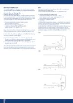
IEC – ( excerpt) This standard applies for the use of electric and electronic equipment and systems for hoisting gear and corresponding equipment. Conductor lines and slipring bodies Protection against direct contact Conductor lines and slipring bodies must be installed or enclosed to ensure that protection is provided against direct contact during usual access to the lifting gear, e.g. over the track platform or crane carrier platform by one of the following protective measures: Ǯ 3 URWHFWLRQE\SDUWLDOO\LQVXODWLQJWKHDFWLYHSDUWV This is the preferred measure. Ǯ 3URWHFWLRQE\HQFORVLQJRUFRYHULQJZLWK...
Open the catalog to page 4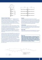
phase spacing Insulator and support distance Conductors L ��, A ��, C �� (Dimension L): distance max. �.� m all other conductors (Dimension L): distance max. �.� m The support brackets are attached to the crane track or respective structures. Phase distance (holes in the support brackets): ��� mm with low voltage, ��� mm with medium voltage up to �� kV. In confined space conditions, the phase distance of conductors L ��, A �� and C �� must be no less than ��� mm and no less than ��� mm for all other conductor types. The support brackets must be aligned during assembly so that the conductors run...
Open the catalog to page 5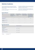
Selection of conductors In order to simplify the selection of the conductors and current collectors, depending on ambient conditions, there is a table for selecting conductors on this page and a table for selecting current collectors on page 32. In addition to the electrical layout, the tables will assist in choosing the correct conductor quickly. These tables limit the dierent conductors in their respective areas of application and provide an overall overview of their application depending on the ambient temperature. In steel mills with a high degree of particle contamination, note F 45/100...
Open the catalog to page 6
Technical Data Type equivalent copper crosssection mm²
Open the catalog to page 7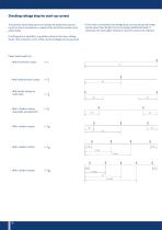
Checking voltage drop for start-up current The position of the feed point can initially be determined according to on-site circumstances, usually at the end of the system (end power feed). If this value is exceeded, the voltage drop can be reduced by changing the power feed length (l) or by arranging additional feeds. If necessary, the next larger conductor may even have to be selected. If nothing else is specied, a guideline value for the max. voltage drop in the conductor of 3% of the nominal voltage can be assumed. Power feed lengths (I): ǣ:LWKHQGIHHGHUFODPS – With feeder clamps at ERWKHQGV...
Open the catalog to page 8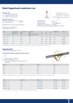
Reference code: / 6WHHO7SURȨOHOLJKWYHUVLRQ 7SURȨOHIRRWZLGWKELQPP &RSSHUFURVVVHFWLRQ PP2) Bending at the factory: 0LQLPXPEHQGLQJUDGLXV5PLQ PP max. support distance: 600 mm ∧ Standard length: 7m ∧ Short sections: on request ∧ Support distance: 2 m in straight runs ∧ Suitable current collectors: DVD, GSV1 The steel prole can be supplied hot galvanized or coated. Bending over the foot, head and lip is possible Bending over the copperhead is not possible with L 20/14 Type Cross section Copperhead mm2 Cross section Steel mm2 Equivalent Total copper cross-section mm2 (1) The last gure of the Ident....
Open the catalog to page 9
Rigid joint Order no. Stainless steel Feeder clamps The feeder clamps are mounted at the intended feed points of the conductor. Type Cu must be soldered onto the copperhead of the conductor. Please clean the contact surfaces and apply contact grease. Order no. Stainless steel Locating clamps Illustration shows an insulator with 2 locating clamps Order no. Stainless steel Galvanized steel Isolating sections 7\SH/ /RRVHGHOLYHU\DVVSDUHSDUW 7\SH0 $VVHPEO\DWWKHIDFWRU\ Max. support bracket distance to the LVRODWLQJVHFWLRQ PP (possi
Open the catalog to page 10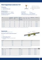
Bending at the factory: 0LQLPXPEHQGLQJUDGLXV5PLQ PP max. support distance: 1000 mm Bending over the foot, head and lip is possible Bending over the copperhead is not possible with F 35/30 Reference code: ) 6WHHO73URȨOH 7SURȨOHIRRWZLGWKELQPP &RSSHUFURVVVHFWLRQ PP2) Cross section Copperhead mm2 Cross section Steel mm2 Standard length: 7m Short sections: on request Support distance: 2.5 m in straight runs Suitable current collectors: GSV 2, GSV 4, GSV 8 The steel prole can be supplied hot galvanized or coated. Equivalent Total copperhead cross-section mm2 (1) The last gure of the Ident. no. states...
Open the catalog to page 11
Order no. Stainless steel The feeder clamps are mounted at the intended feed points of the conductors. Type Cu must be soldered onto the copperhead of the conductor. Please clean the contact surfaces and apply contact grease. Feeder clamps Order no. Stainless steel (1) not illustrated / 265 mm long connection terminals can be used as rigid joints at he same time Locating clamps Illustration shows an insulator with 2 locating clamps (x point) Order no. Stainless steel Galvanized steel Isolating sections
Open the catalog to page 12
Reference code: ) 6WHHO7SURȨOH 7SURȨOHIRRWZLGWKELQPP &RSSHUFURVVVHFWLRQ PP2) Bending at the factory: 0LQLPXPEHQGLQJUDGLXV5PLQ PP max. support distance: 1200 mm Bending over the copperhead is not possible with F 45/50 Cross section Copperhead mm2 Standard length: 7m Short sections: on request Support distance: 2.5 m in straight runs Suitable current collectors: GSV 2, GSV 4, GSV 8 The steel prole can be supplied hot galvanized or coated. Bending over foot, head and lip is possible Cross section Steel mm2 Equivalent Total copper crosssection mm2 (1) The last gure of the Ident. no. states the individual...
Open the catalog to page 13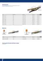
Expansion joint with increased expansion value (e.g. building expansion joint) (required for system lenths over 100 m) Order no. Stainless steel
Open the catalog to page 14All VAHLE catalogs and technical brochures
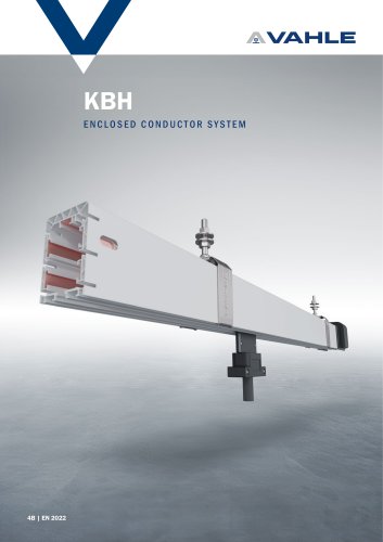 Enclosed conductor system KBH
36 Pages
 spring-operated cable reels
40 Pages
 APOS Magnetic (gliding)
2 Pages
 APOS Optic
12 Pages
 Motor powered cable reels
24 Pages
 APOS Magnetic (touchless)
8 Pages
 SMGM
SMGM20 Pages
 SMGX
SMGX20 Pages
 CPS 20kHz
24 Pages
 Charging contacts
8 Pages
 CPS 140kHz
32 Pages
 Compact conductor system VKS
32 Pages
 Compact conductor system VKS10
28 Pages
 Shuttle Charging System
2 Pages
 Compact conductor system VCL
8 Pages
 Insulated conductor system U10
28 Pages
 Product Portfolio
16 Pages
 Festoon system
28 Pages
 Enclosed conductor system MKH
40 Pages


- Analysis software solution
- Fixed reel
- Monitoring software solution
- Battery charger
- Retractable reel
- Visualization software solution
- Cable reel
- Motorized reel
- Positioner
- Mobile reel
- Electric vehicle battery charger
- Festoon system
- Electric positioner
- Smart battery charger
- Metal cable trolley
- Floor-standing battery charger
- VAHLE conductor rail
- Linear positioner
- ISO battery charger
- Forklift truck battery charger