


- Company
- Products
- Catalogs
- News & Trends
- Exhibitions
Insulated conductor systems U15 | U25 | U35

Insulated conductor systems U15 | U25 | U35
The document provides comprehensive technical specifications and installation guidelines for insulated conductor systems U15, U25, and U35. These systems are designed for applications such as cranes, monorail systems, and data transmission, with varying ampacity levels.
Insulated conductors adhere to international safety standards (VDE 0100, VDE 0470) and are finger-safe. They are suitable for voltages over 25V AC or 60V DC. Standard lengths are 6m for U15 and U25, and 6.25m for U35, with shorter sections available.
U15 is for light applications up to 100A, U25 for medium applications up to 450A, and U35 for heavy-duty applications up to 1250A. Selection is based on ampere load and environmental conditions.
- Joint Splices: Ensure mechanical and electrical continuity with insulated covers.
- Expansion Sections: Necessary for systems over 100m (U15) or 150m (U25/U35) to handle temperature changes.
- Feed Terminals: Installed at conductor joints for power connection.
- End Caps: Seal open ends of conductors.
- Transfer Guides: Available for various transfer applications.
- Collectors: Single or double collectors are used based on system needs.
Conductors can be installed side by side with minimal space. Insulators are recommended in harsh environments to prevent electrical flashover. Minimum distances must be maintained to avoid pinching risks.
Systems are approved by SEV, CSA, and UL. They offer chemical resistance for standard and heat-resistant designs. Safety measures include touch-proof installations and maintaining minimum distances between components.
Includes dielectric strength, surface resistance, and mechanical properties, with specific data for standard and high-temperature shrouds.
Detailed specifications for components and systems related to insulated conductors and current collectors, including attachment hardware, dimensions, weight, and order numbers.
Instructions for installation and ordering of components like insulated conductors, collector brackets, and expansion sections. Guidelines for feed points arrangement and transfer funnels usage.
Outlines standards for collectors in different environments, recommendations for aggressive environments, and limitations on continuous current. Specifies necessary spacing and support for conductor brackets.
Includes tables listing types, capacities, dimensions, weights, and order numbers for components. Key data includes current collector specifications, conductor rail types, and expansion section details.
- Collectors at low speeds or stationary should operate at 50% of continuous current.
- Special collectors for aggressive environments available upon request.
- Support spacing and conductor spacing guidelines are crucial for proper installation.
Lists UDV and UE components, specifying weight, phase, and ground details, including high-temperature shrouds and accessories like feed terminals and insulated hangers.
Includes rail holders, locating clamps, contact grease, and end caps, with weight and order numbers, installation guidelines, and usage recommendations.
Details current collectors and components, including spares for different collector types, with weight, order numbers, and configurations for lateral opened conductor systems.
Instructions for arranging and ordering U35 system components, including expansion sections, bolted joint splices, and insulated hangers. Includes a questionnaire for specifying requirements for insulated conductor systems.
Describes the earthing spider system for earthing and short-circuiting phase conductors with the ground conductor during maintenance, specifying type, copper section of wire rope, and order numbers.
Catalog excerpts

U15 | U25 | U35 INSULATED CONDUCTOR SYS TEMS
Open the catalog to page 1
INSULATED CONDUCTORS U 15 – U 25 – U 35 Index Basic description Selection of conductors Insulated conductors Joint splices Expansion sections Feed terminals Locating clamps Insulated hangers Rail holders Insulators Compact hangers, bracket profiles Attachment hardware Transfer guides Sectionalizing End caps Transfer funnels Collectors Connecting cables Collector brackets, Cable attachment clamp Contact grease Components for collectors, Spare parts Brush wear indicator Brackets, Snap-on brackets, Mounting brackets Examples for ordering, Arrangement Installation tools Earthing spider system Questionnaire...
Open the catalog to page 2
GENERAL SELECTION OF CONDUCTORS ENGINEERING DATA Pages 4 – 5 U 15 For light cranes and hoists/elevators, self-propelled monorail carriers, automated storage and retrieval systems, assembly and test tracks, motor powered gates and doors, for all kinds of data and signal transmission, etc. Ampacity up to 100 A U 25 For bridge- and portal crane electrification, stacker cranes, heavy monorail systems, amusement & rapid transit rides, construction- and maintenance lifts etc. Ampacity up to 450 A U 35 Applications as U 25; however for heavy duty – Ampacity up to 1250 A Questionnaire Page
Open the catalog to page 3
INSULATED CONDUCTORS U 15 – U 25 – U 35 Joint splices General The insulated conductors U15, U25 and U35 are designed according to VDE 0100, which is today's international safety requirement and are finger safe to VDE 0470, part 1 (EN 60 529) (Protection code IP 23 in hanging arrangement) For collectors is this touch proof only valid if the carbons are completly inside the bus bar. In hand areas installed conductor systems, in which the collectors leave the bus bar due to site requirements, the customer has to make sure that touch proof is created on site. (e.g. barriers or disconnection) This...
Open the catalog to page 4
INSULATED CONDUCTORS U 15 Conductor code: U = unipole insulated conductor 15 = shroud size 25 = conductor cross sectional area (mm2) C = copper conductor E = stainless steel conductor RH = Radius Horizontal curve Length: 6 m is standard length, shorter lengths are available Conductor spacing: on compact hangers on standard hangers with insulators Max. support distance: in straight systems and inner or outer curves and with lay out of horizontal curves abover RH = 5 m(2): min. 50 mm 1000 mm with single collectors Curves: 800 mm with double collectors (KDST) factory prepared or on site with curve...
Open the catalog to page 5
ACCESSORIES FOR U 15 Bolted joint splice applicable as feed terminal, too. Expansion sections consisting of exponsion joint installed with a joint splice on a condcutor section of 1 m length are required in systems from 100 m length. This length has to be counted into the total length of the system. clamp dimensions of UDVN Standard shroud, color green Type High temperature shroud, color gray Order- No. Feed terminals Corresponding to UV 15 K Connection cross section max. 2 single cores each 6 mm2 Weight kg Cable lug and cable by others with stainless steel hardware max. ampacity 70 A max. ampacity...
Open the catalog to page 6
Pictures shows a insulated hanger with 2 locating clamps Rail holders to be used with insulator only cantilever = 3000 N creapage distance = 60 mm Type Compact hangers 2- to 7-pole With this compact hangers is a combination of any number of poles possible. A 18 Conductor spacing 18 mm. The hanger KA 15 is for direct bolting. The hanger KH 15 has to be inserted in bracket profile. Type Bracket profiles 28/12 incl. locking hardware with stainless steel hardware Longer brackets furnished on s
Open the catalog to page 7
Attachment hardware for compact hangers, insulated hangers and insulators Transfer guides for monorail systems with and without feed terminals (also serving for anchor points in conjunction with BFU 15 B) c/w feed USE 15 T (cable terminal 6.3 mm x 0.8 mm) Arrangement of the transfer guides at switches max. gap between opposite transfer guides: 6 mm for straight transfers 10 mm for oblique transfers max. vertical and horizontal offset: 2 mm left hand version feed terminal US 15 T (USE 15 T) US 15 TS (USE 15 TS) The oblique transfer guides are marked right hand version Anchor bars for monorail...
Open the catalog to page 8
ACCESSORIES FOR U 15 Transfer guides (no anchor point function) max. air gap 6 mm max. vertical and horizontal offset ± 2 mm 10 feed terminal US 15 w/o USE 15 c/w separately available: SE 15 feed plug Isolating sections Type M: factory assembled per system layout Type L: loose delivery as a single item On both sides of the isolating section a hanger has to be considered. Distance max. 200 mm from center isolating section. Conductors and hangers have to be ordered separately. Length of isolating piece A Isolating assemblies 2 x LT/U 15 1 x flat plug 2 x LT/U 15 2 x flat plug Isolating assembly...
Open the catalog to page 9
TRANSFER FUNNELS FOR U 15 Transfer funnels for KSTU 30/55 EFT U 15-2 - KSTU EFT U 15-3 - KSTU EFT U 15-4 - KSTU EFT U 15-5 - KSTU EFT U 15-6 - KSTU EFT U 15-7 - KSTU EFT U 15-8 - KSTU Transfer funnels for KSTLU / KDSTLU EFT U 15-2 - KDSTLU EFT U 15-3 - KDSTLU EFT U 15-4 - KDSTLU EFT U 15-5 - KDSTLU EFT U 15-6 - KDSTLU EFT U 15-7 - KDSTLU EFT U 15-8 - KDSTLU Higher speeds on request.
Open the catalog to page 10
TRANSFER FUNNELS AND CURRENT COLLECTORS FOR U 15 335 Transfer funnels for KSFU 25 EFT U 15-2 - KSFU 44 EFT U 15-3 - KSFU 62 EFT U 15-4 - KSFU 80 EFT U 15-5 - KSFU 98 EFT U 15-6 - KSFU 116 EFT U 15-7 - KSFU 134 EFT U 15-8 - KSFU 152 Collectors c/w 2 m cable; contact pressure ca. 5 N A < 300 mm conductor support spacing 0.8 m A > 300 mm conductor support spacing 1.0 m Connecting cable A/ D max/ mm2 mm KST 30 KST 55 KSTL 30 KSTL 55 KSTU 30(3) KSTU 55(3) with double collector plug terminal 6.3 x 0.8 for FLA 2.5 or WFLA 2.5 plug terminal 6.3 x 0.8 for FLA 2.5 or WFLA 2.5 Lift ±10 mm,swivel ±15 mm,...
Open the catalog to page 11
COLLECTORS FOR U 15 Double current collector max. ampacity: 1 flat plug 25 A, 2 flat plugs 2 x 20 A plug terminal 6.3 x 0.8 for WFLA 2.5 Lift ±10 mm, swivel ±10 mm, contact pressure: ca. 3.5 N per brush Connecting cable to be ordered seperately. Type(1) Order- No. phase - black ground - yellow plug terminal 6.3 x 0.8 for FLA 2.5 or WFLA 2.5 Compact current collectors(2) max. ampacity: 1 flat plug 25 A For conductor spacing of 18 mm; Lift & swivel ± 15 mm Contact pressure: ca. 3.5 N per brush Ground at No. 4, 3-pole at No. 3 other position on request. For safety reasons during maintenance ground...
Open the catalog to page 12All VAHLE catalogs and technical brochures
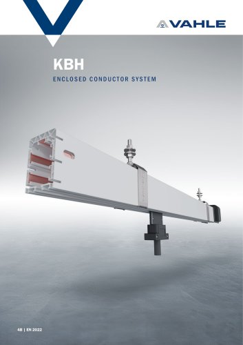 Enclosed conductor system KBH
36 Pages
 spring-operated cable reels
40 Pages
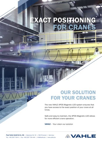 APOS Magnetic (gliding)
2 Pages
 APOS Optic
12 Pages
 Motor powered cable reels
24 Pages
 APOS Magnetic (touchless)
8 Pages
 SMGM
SMGM20 Pages
 SMGX
SMGX20 Pages
 CPS 20kHz
24 Pages
 Charging contacts
8 Pages
 CPS 140kHz
32 Pages
 Compact conductor system VKS
32 Pages
 Compact conductor system VKS10
28 Pages
 Shuttle Charging System
2 Pages
 Compact conductor system VCL
8 Pages
 Insulated conductor system U10
28 Pages
 Product Portfolio
16 Pages
 Open conductor system
48 Pages
 Festoon system
28 Pages
 Enclosed conductor system MKH
40 Pages

- Analysis software solution
- Fixed reel
- Monitoring software solution
- Battery charger
- Retractable reel
- Visualization software solution
- Cable reel
- Motorized reel
- Positioner
- Mobile reel
- Electric vehicle battery charger
- Festoon system
- Electric positioner
- Smart battery charger
- Metal cable trolley
- Floor-standing battery charger
- Linear positioner
- ISO battery charger
- Forklift truck battery charger