


- Company
- Products
- Catalogs
- News & Trends
- Exhibitions
Insulated conductor system U10

Insulated conductor system U10
The U10 insulated conductor system is designed according to VDE 0100 standards, ensuring safety against accidental human contact as per VDE 0470, part 1 (DIN EN 60529), with a protection classification of IP 21. It is approved for indoor use only and can consist of multiple conductors with minimal space requirements. Systems with operating voltages above 25 VAC or 60 VDC require additional safety measures like barriers or shut-off switches.
The conductor system is available in various versions with a standard phase distance of 14 mm. It is suitable for indoor applications only, with a standard section length of 6 meters. The system supports both copper and stainless steel conductors, with specific configurations for different environmental conditions.
- Compact Hangers: Used for installation, maintaining a 14 mm phase distance.
- Joint Splice/Feed: Connects conductor sections mechanically and electrically.
- Feed Terminals: Allow feed connections at joint splices and other locations.
- Transfer Guides: Protect conductor ends and facilitate reliable passage of collector brushes.
- Isolating Assemblies: Interrupt electrical current flow, used for control functions and maintenance sections.
- Expansion Sections: Allow for expansion capability.
The system complies with various international standards, including DIN, EN, ISO, IEC, and UL. Safety measures include maintaining a minimum safety distance of 0.5 meters between the conductor/current collector arrangement and other equipment.
Installation tools and guidelines are provided to ensure proper setup and maintenance. The system includes various components like carbon brushes, springs, and connecting cables, each with specific installation requirements.
The document provides detailed specifications and ordering information for various electrical components used in conductor systems, including compact hangers, locating clamps, current collectors, connecting cables, terminal boxes, and brush wear indicators.
The document lists various tools and components for installation, including curve tools, filler rods, crosscut saws, deburring files, conductor punch tools, adjustment jigs, transfer guides, joint splice/feed assembling tools, locking pin drivers, conductor removal tools, and installation toolboxes.
Tools are specified for forming curves, cutting profiles, deburring, punching conductor profiles, and assembling joint splices.
This section includes a detailed questionnaire for planning installations, covering aspects such as installation concept, type of application, conductor orientation, installation height, and environmental requirements.
Details on installation location, ambient temperature, relative humidity, and extraordinary environmental conditions are provided to ensure proper installation and operation.
Options for data transmission include SMGM, Powercom, Semi-Wave, and CAN-Bus systems. Positioning systems include APOS Optic and APOS Magnetic.
The document notes that the system is not suited for outdoor installation and provides a framework for quantity and configuration of components.
Contact details for Paul Vahle GmbH & Co. KG are provided for further inquiries and support.
Catalog excerpts
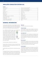
GENERAL INFORMATION The U10 insulated conductor system has been designed in accordance with VDE 0100. It complies with current conductor system safety require- UL Certification. Please consult us when ordering. ments and protects against accidental human contact as stipulated by VDE 0470, part 1 (DIN EN 60529), (protection classification IP 21). Compact hanger Compact hangers are used for conductor installation and will also pro- Fig. 1 illustrates that the VDE test “finger” cannot make contact with vide and maintain the defined 14 mm phase distance. Hanger center current carrying components....
Open the catalog to page 2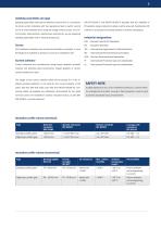
Isolating assemblies (air gap) Isolating assemblies interrupt the electrical current flow in a conductor. DIN EN 60204-1 and DIN-EN 60204-2 stipulate that the reliability of To utilize current collectors with the operational task to switch current PE systems using conductor brushes must be ensured. Doubling the PE on/off is only permitted when using low energy control current. For con- collector is a practical and simple solution to achieve compliance. trol function, feed sections, maintenance sections etc. we are supplying Industrial designations isolating assemblies with or without SE feed...
Open the catalog to page 3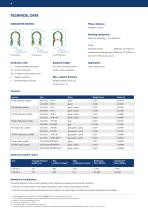
TECHNICAL DATA CONDUCTOR SECTIOn 11.2 RH Radius horizontal curve Bending conductors RH Radius horizontal curve Horizontal curves RH Radius horizontal curve Inward/outward facing curves 5000 mm ≥ R ≥750 mm PE-VPN Standard Conductor code Supplied length U = Unipole insulated conductor Indoor systems only shorter sections available 25 = Conductor cross section (mm²) C = Copper conductor E = Stainless steel conductor Straight sections: 0.6 m (2′′) Curves: 0.3 m (1′′) Versions Version Phase (standard profile) green, yellow green, yellow PE (standard profile) PE-VPN (standard profile) green, yellow...
Open the catalog to page 4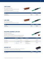
Max. 2 x 40 A continuous current Compensates for up to 4 mm section expansion/contraction caused by temperature fluctuations Connecting cables not included, please order from page 15 Type LINE FEED Max. 2 x 50 A continuous current Connecting cable not included, please order from page 15 Type Max. 40 A continuous current Two halves are joined during installation Feed clip SE 10 with tab connector 6.3 x 0.8 mm (max. continuous current 40 A), at least one additional compact hanger required for each isolating assembly. Type SPACER CLIP to provide support for isolating assembly by filling gap between...
Open the catalog to page 5
EXPANSION SECTION single conductor, to be completed at installation site Expansion capability of expansion section must equal the max. expansion capability of the EMS track. Two fix points are required with each expansion section. Please order as required by the EMS track layout. An additional compact hanger is required for each 15 mm expansion capability. Please add to your order as required. TRANSFER GUIDES Max. vertical and horizontal offset ±3 mm respective Transfer guide for phase + PE Max. 40 A continuous current BFU 10 B Transfer guide US10 (straight) 37 BFU 10 A Transfer guide US10 S...
Open the catalog to page 6
ANCHOR BRACKET (ALUMINUM) FOR TRANSFER GUIDES to be bolted to the track Two holes to be drilled through the EMS track to screw on the anchor bracket from the back. Kit comprises: 1 x anchor bracket, 2 x hex screws M5 with lock washer, 2 x roll pins 2 x 20. to be used when EMS track has been cut obliquely (see drawing page 6). for system height(1) = 16.5 mm Type BFU 10V for system height(1) = 10.5 mm Socked head screws inserted at front of EMS track. Anchor bracket kit consists of: 1 x anchor bracket, 2 x socket head screws M4, 2 x roll pins. Type (1) System height = distance contact surface to...
Open the catalog to page 7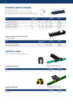
Screw material must be selected according to the web thickness. These compact hangers may be combined to support any number of conductors. Compact hanger KA10 (used with screws) incl. adapter for SMGM Type LOCATING CLAMPS 2 USK10 location clamps are required for each fix point Locating clamp standard Illustration shows positioning of the two Locating clamps at a compact hanger Locating clamp PE-VPN Illustration shows positioning of the two locating clamps at a compact hanger STANDARD COMPACT HANGERS
Open the catalog to page 8
COMPACT HANGERS (CUSTOMER SPECIFIC) Engineered and manufactured to fit customer specific EMS track
Open the catalog to page 9
COMPACT CURRENT COLLECTOR KDS2/40 Connection cable Type WFLA 2.5 mm2 for installations with mostly one-way travel with 1 x 0.5 m connecting cable type WFLA 2.5 Max. current: Contact pressure: approx. 3.5 N per contact brush Connecting cable: 2.5 mm2 type WFLA 2.5 high flex included PE standard at No. 4 position, variations are possible. PE makes contact first when entering conductors. Base plate Order No. with PE-VP Single conductor available with 0.5 m connecting cable SA-KDS2/40/04PH-88/15-0.5 Phase, black Current collector sets (trailing unit) Single conductor on base plate. PE standard at...
Open the catalog to page 10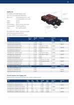
for installations requiring bi-directional travel with 1 x 0.5 m connecting cable type WFLA 2.5 1 connecting cable 2.5 mm2, 25 A Contact pressure: approx. 3.5 N per contact brush Connecting cable: 0.5 m, high flex included Connection cable Type WFLA 2.5 mm2 PE standard at No. 4 position, variations are possible. Dimensions of base plate see KDS2/40. PE makes contact first when entering conductors. Type Base plate Order No. with PE-VP Single conductor available with 0.5 m connecting cable Phase, black Current collector sets (trailing unit) Single conductor on base plate. PE standard at No. 4 position,...
Open the catalog to page 11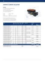
COMPACT CURRENT COLLECTOR KUFU25 for installations requiring bi-directional travel for entry funnel EFT10-KUFU with 1 m connecting cable type FLA 2.5 Contact pressure: approx. 3.5 N per contact brush PE at No. 4 position, with 3 conductors at No. 3, with 2 conductors at No. 2. Variations are possible. PE makes contact first when entering conductors. Base plate Order No. with PE-VP with PE-Standard Phase, black Single conductor available, without connecting cable 0.051
Open the catalog to page 12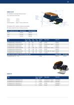
for installations requiring bi-directional travel Flat plug 6.3 x 0,8 for FLA or bolted connection Contact pressure: approx. 7 N per contact brush PE standard at No. 4 position, variations are possible. PE makes contact first when entering conductors. max. continuous current Base plate Single conductor available, without connecting cable SA-KESR32-55F/14 ... -31-0 Phase, black Base plate
Open the catalog to page 13All VAHLE catalogs and technical brochures
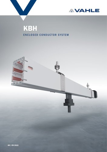 Enclosed conductor system KBH
36 Pages
 spring-operated cable reels
40 Pages
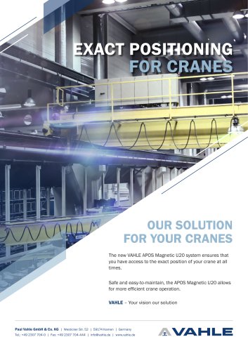 APOS Magnetic (gliding)
2 Pages
 APOS Optic
12 Pages
 Motor powered cable reels
24 Pages
 APOS Magnetic (touchless)
8 Pages
 SMGM
SMGM20 Pages
 SMGX
SMGX20 Pages
 CPS 20kHz
24 Pages
 Charging contacts
8 Pages
 CPS 140kHz
32 Pages
 Compact conductor system VKS
32 Pages
 Compact conductor system VKS10
28 Pages
 Shuttle Charging System
2 Pages
 Compact conductor system VCL
8 Pages
 Product Portfolio
16 Pages
 Open conductor system
48 Pages
 Festoon system
28 Pages
 Enclosed conductor system MKH
40 Pages


- Analysis software solution
- Fixed reel
- Monitoring software solution
- Battery charger
- Retractable reel
- Visualization software solution
- Cable reel
- Motorized reel
- Positioner
- Mobile reel
- Electric vehicle battery charger
- Festoon system
- Electric positioner
- Smart battery charger
- Metal cable trolley
- Floor-standing battery charger
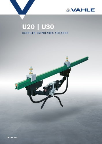
- VAHLE conductor rail
- Linear positioner
- ISO battery charger
- Forklift truck battery charger