Compact conductor system VKS10
1 /28Pages

Compact conductor system VKS10
1 /28Pages
Catalog excerpts
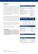
GENERAL Electrical properties hazard protected safety conductor rails. They consist of a flatformed insulated housing with integrated copper conductors. These conductors sections than shown on page 7 are possible. If the cross-section of the Special electrical strength IEC 60093 N-conductor is smaller than the cross-section of the outer conductor, it must be protected against overcurrent and short-circuits in accordance Flame resistant, self extinguishing, UL 94 V0 VAHLE’s compact conductor system type VKS10 is compact and shock are protected according to European standard EN 60529. They comply...
Open the catalog to page 3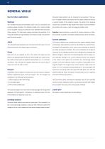
GENERAL VKS10 Use for indoor applications Conductor dead sections can be mounted at any position of the system. The plastic inserts are pushed into the copper profiles and ensure a smooth transfer of the collector brushes. The length of the isolating The insulated housing accommodates up to max. 10 conductors and section has to consider the total length of the carbon brush and whether provides reliable insulation. The standard length is 6 m, shorter lengths the carbon brush must or must not bridge the isolation area. can be supplied. The ground conductor rail is identified with continuous yellow...
Open the catalog to page 4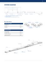
Fixpoint hanger Sliding hanger = Length of conductor section (standard length: 1 m – 6 m, respectively short length) = Support distance for straight runs: max. 1.2 m, in curves 0.6 m = Overhang (max. 350 mm) = Distance to be allowed for conductor system expansion (min. 50 mm) Max. hanger distance Conductor system VKS10 In straight runs Arrangement 1 min. 180 (KESR) min. 250 (KST, KESL) Support profile VTP10 On rack uprights Horizontal arrangement Line feed Hanger support profile Hanger conductor system Joint conductor system
Open the catalog to page 5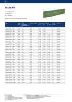
Standard lengths: 6 m Cold stores: 4 m right side HS = with ground Attention: Joints to be ordered separately (see page 8) left side Conductor cross section L1–L3 At 80 % duty cycle 2 conductors per phase Powerail projecting length 34 mm at 20°C ambient Consult factory in case of circuits incl. N conductors Not with UL-approval: UUL = 600 V Complete types e. g. VKS10-6/60-2000HSA for 2 m. Order No. 780042 The 4-digit number (in bold) in the type indicates the length of the section in mm. • T he last number of the or
Open the catalog to page 6
CURVED SECTIONS Copper cross section min. 25 mm2 Inside bend R Max. length of bend = 5.3 m Hanger distance Inside bend Outside bend = conductors outside (not shown) Bends are supplied with straight ends, each 250 mm long. Type Surcharge inside bend lateral (R > 1000) Surcharge outside bend lateral (R > 1500) (1) Smaller radius on request (2) In case of hall expansion joints please consider expansion sections (on request). (3) Conductor rails connected in
Open the catalog to page 8
Fixpoint hanger Sliding hanger on C-rail consisting of hanger clamp and fixing screw and C-rail on C-rail consisting of hanger clamp and C-rail Fixing screw Sliding hanger for support profile VTP 10 consisting of hanger and fixing screw for support profile VTP 10 consisting of hanger clamp Fixpoint hanger Fixing screw Support profile Can be used right or left handed. Terminal box supplied loose, Supplied loose as individual part with fixing screws. only in conjunction with line feed VLS(2) (1) Cable glands 2 x ST-M 40 x 1.5 for Ø = 19 – 28 mm 1 x ST-M 20 x 1.5 for Ø = 7 – 13 mm (2) Please order...
Open the catalog to page 9
LINE FEEDS Line feed VLS length 1m for direct connection of single core cables M6 terminal with special cable shoe for single core cables; 35 mm2 (up to cable Ø 8.5 mm) for 140 A, left side or feed bolts for 60 A conductor system right side 1 m section to be ordered separately Opening for cable outlet
Open the catalog to page 10
LINE FEEDS Line feed VNS right side Shown with terminal box Cable gland: Connecting cable: Cable connection: left side 1 m section to be ordered separately. Cable payout left, standard Type ISOLATING SECTION(1) Specify the position of the isolating sections and the designation of the conductor profiles, which are to be separated, when ordering. The sections are factory assembled, loose delivery on request. Type (1) For specification of the conductor profile refer to page 6 (2) Length of the conductor dead section (longer dead
Open the catalog to page 11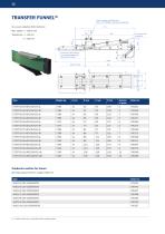
Auxiliary support and fixing claw (Order. No. 780088) to be ordererd separately for current collector KSTU 30-63-14 Conductor system VKS 10 to be ordererd separately Type see table below 1365 Support profile Conductor section for funnel (all cross sections 25 mm2, length 1365 mm) Type (1) Transfer funnel only in combination with conductor section.
Open the catalog to page 12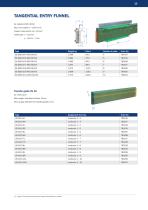
TANGENTIAL ENTRY FUNNEL 87 Max. entry speed v = 100 m/min. Copper cross section min. 25 mm2 Transfer guide VU 10 for cross travel Max. height- and lateral off-set: ±2 mm Max. air gap between the transfer guides: 5 mm (1) Length of the conductor dead section (lon
Open the catalog to page 13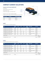
COMPACT CURRENT COLLECTORS Compact current collector KESR 32-55 Distance between conductors: 14 mm Lift and swifel: ±15 mm Contact pressure: approx. 7 N per carbon brush Flat plug 6.3 x 0,8 for FLA or bolted connection PE (ground) on No. 4, (other combinations possible) The ground collector always moves first when entering the conductor system. Max. current Flat plug Bolted connection KESR-F for connecting cables with flat plug, see page 19 Type Base plate KESR-S for connecting cables with bolted connection, see page 19 Type Base plate
Open the catalog to page 14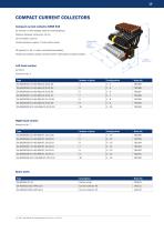
Compact current collector KESR 63S for reverse run with adapter plate and clamping block Distance between conductors: 14 mm Lift and swifel: ±15 mm Torque setting: 1.7 Nm(1) (bolted connection) Contact pressure: approx. 7 N per carbon brush (Installation dimension) COMPACT CURRENT COLLECTORS PE (ground) on No. 4, (other combinations possible) The ground collector always moves first when entering the conductor system. Left hand version as shown Ground on No. 4 Type Right hand version Ground on No. 7 Spare parts Type Carbon brush (1) Max. cross section of connecting
Open the catalog to page 15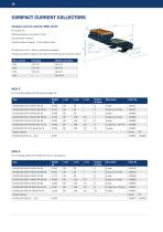
COMPACT CURRENT COLLECTORS Compact current collector KESL 32-63 Distance between conductors: 14 mm Contact pressure: approx. 7 N per carbon brush PE (ground) on No. 4, (other combinations possible) The ground collector always moves first when entering the conductor system. Max. current Flat plug Bolted connection DF4 Flat plug 6.3 x 0,8 for FLA or bolted connection KESL-F for connecting cables with flat plug, see page 19. Type Base plate KESL-S for connecting cables with bolted connection, see page 19. Type Base plate
Open the catalog to page 16All VAHLE catalogs and technical brochures
 Enclosed conductor system KBH
36 Pages
 spring-operated cable reels
40 Pages
 APOS Magnetic (gliding)
2 Pages
 APOS Optic
12 Pages
 Motor powered cable reels
24 Pages
 APOS Magnetic (touchless)
8 Pages
 SMGM
SMGM20 Pages
 SMGX
SMGX20 Pages
 CPS 20kHz
24 Pages
 Charging contacts
8 Pages
 CPS 140kHz
32 Pages
 Compact conductor system VKS
32 Pages
 Shuttle Charging System
2 Pages
 Compact conductor system VCL
8 Pages
 Insulated conductor system U10
28 Pages
 Product Portfolio
16 Pages
 Open conductor system
48 Pages
 Festoon system
28 Pages
 Enclosed conductor system MKH
40 Pages


- AMOT analysis software
- Fixed reel
- AMOT monitoring software
- Retractable reel
- Battery charger
- AMOT visualization software
- Cable reel
- AMOT positioner
- Motorized reel
- Mobile reel
- Electric vehicle battery charger
- Electric positioner
- Festoon system
- Smart battery charger
- Metal cable trolley
- Floor-standing battery charger
- Linear positioner
- Single-axis positioning positioner
- ISO battery charger