


- Company
- Products
- Catalogs
- News & Trends
- Exhibitions
Compact conductor system VKS

Compact conductor system VKS
VAHLE's VKS and VKL conductor systems are designed for efficient space usage and safety, adhering to VDE 0470, part 1 (EN 60529) with protection code IP 21. These systems are suitable for indoor and roof-covered applications, supporting industrial uses such as hoists, cranes, and machine tools. They are UL-approved and comply with electrical, mechanical, and fire safety regulations.
The VKS system supports a maximum ampacity of 140 A and voltage up to 690 V, while the VKL system supports up to 30 A and 400 V. Both systems feature high electrical strength and flame resistance. Conductor materials include copper with varying cross-sections, and the systems are resistant to various chemicals at specified temperatures.
Both systems use plastic housings to hold conductors, with VKS accommodating 3 to 6 conductors and VKL up to 5. Installation options include lateral or suspended mounting, with standard section lengths available. Jointing materials, hangers, and brackets are provided for secure installation. Collectors are designed for continuous current ratings and are equipped with spring-loaded carbon brushes for reliable contact.
Layout planning involves careful consideration of support spacing, expansion allowances, and the use of end caps and feeds. The systems can be customized with various components like transfer guides and expansion sections to suit specific operational needs.
For environments with aggressive conditions or specific applications like data transmission, consultation with the factory is advised. Proper documentation, such as drawings or sketches, is recommended to expedite order processing.
The VKS and VKL systems offer versatile and safe solutions for industrial conductor applications, with a range of components and configurations to meet diverse operational requirements.
- Max Ampacity: Bolted connections range from 32 A to 63 A depending on the AEA type, while flat plug connections range from 32 A to 55 A.
- Phase Distance: 18 mm for compact collectors.
- Contact Pressure: Approximately 7 N per carbon.
- Adaptors: Available for compact collectors with different pole configurations and dimensions.
- Connecting Cables: High flexible cables for both flat plug and bolted connections, with operating conditions from -15°C to 70°C.
- Towing Arms: Available for current and control collectors, with specific order numbers and weights.
- Spare Parts: Includes brushes, collector arms, cover caps, and connecting cables with detailed order numbers and weights.
- Installation Height: Specified for various components, with torque requirements for bolted connections at 1.2 Nm.
- System Length and Support Spacing: Standard sections have a length of 4 m with a support spacing of 1000 mm, and a maximum system length of 100 m.
- Curved Sections: Curved sections are available with specific radius requirements and support spacing.
- Detailed order numbers are provided for each component and accessory, including joint materials, end caps, and line feeds.
- Examples for ordering VKS and VKL systems are included, specifying quantities and types of conductor rails and accessories needed for straight and curved tracks.
The document lists various components and their specifications for a conductor rail system. Key components include conductor rails of varying lengths and types, joint materials, sliding hangers, end caps, and collectors. Specific order numbers and types are provided for each component, indicating their dimensions and intended use, such as for inside or outside curves.
The document includes an example for ordering conductor rails, detailing the required quantities, descriptions, types, and order numbers. It also outlines the process for preparing a quotation for curved tracks and conductor systems with isolating sections, requiring sketches from the customer.
Recommendations for the installation of the conductor system are provided, including the mounted position, support distance, and the number of consumers per system. The document advises on the use of specific types of motors and provides a questionnaire to gather detailed information about the installation environment and requirements.
The document contains diagrams illustrating the layout of conductor rails and their positioning. It specifies the dimensions and radii for curves and the arrangement of copper conductors on the left and right sides. The questionnaire section collects data on operating voltage, track length, number of conductors, and environmental conditions.
Important parameters include the maximum support distance for the conductor system, the ambient temperature range, and the travel speed in curves and transfers. The document also highlights the need to consider voltage drop from the feed point to the consumer and the power consumption of individual consumer loads.
The document provides contact details for Paul Vahle GmbH & Co. KG, including their address, phone number, email, and website, along with a note to find local contacts through their website.
Catalog excerpts

VKS AND VKL COMPACT CONDUCTOR SYS TEMS
Open the catalog to page 1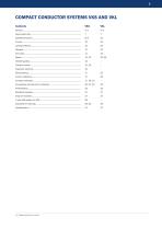
COMPACT CONDUCTOR SYSTEMS VKS AND VKL Contents VKS (1) Please enclose to your i
Open the catalog to page 3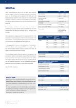
GENERAL Electrical properties systems, designed to prevent any accidental contact and hazard to per- sonnel and are test finger proof to regulations VDE 0470, part 1 (EN Allowed voltage Special electrical strength IEC 60093 Conductor system installations within reach of hand require a special protection on the part of operator against accidental touch of current Flame resistant, self extinguishing, UL 94 V0 VAHLE conductor systems VKS and VKL are space saving conductor 60529), protection code IP 21. They comply with the accident and VDE regulations in electrical, mechanical and fire engineering...
Open the catalog to page 4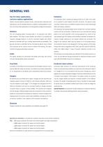
GENERAL VKS Use for indoor applications, roof-over outdoor applications Collectors The collectors have a continuous rating of 20 A up to 120 A. One collec- Hoists, monorail systems, stacker cranes, machine tools, production and tor is required for each phase and earth conductor. The ground collec- testing lines, also for sliding switches, turntables, hoisting stations, trans- tors have a yellow colour and different attachments to avoid interchange- fers, and many other applications, including data and signal transmission. ability with phase collectors. The collectors have spring loaded carbon...
Open the catalog to page 5
GENERAL VKL Use Indoor applications Designed for small current loads and serve for the power supply of light To support the conductor rail to the crane track mounting brackets avail- cranes and for control current systems. The VKL conductor rail can also able (siehe Seite 27). be used for hoists, jib cranes, power tools, machine tools, electrically operated gates, testing lines, and other applications. Collectors The glider type collectors are guided at the PVC housing. They are sup- plied with 1 m long connecting cable. Longer cables are available upon The plastic housing holds up to 5 conductors....
Open the catalog to page 6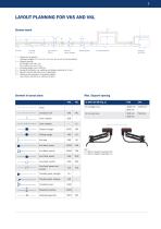
System layout Line feed VLS/VLE Joint material SVN/LV Sliding or fixpoint hangers Transfer guides Line feed VNS/VNK L = Conductor rail section (Standard lengths: 1 m, 2 m, 3 m, 4 m, 5 m, 6 m or cut to suit the system) L1 = Support spacing for straight runs: max. 1 m for curved runs: max. 0.5 m L2 = Extending length (max. 200 mm) L3 = Air gap for transfers, e. g. switches and dropout sections (3–5 mm) L4 = Space to remove feed box cover, if applicable L5 = Clearance for expansion of conductor system (min. 50 mm for VKS; min. 150 mm for VKL). Symbols in layout plans Max. Support spacing at KSTU...
Open the catalog to page 7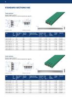
STANDARD SECTIONS VKS 3-pole sections Standard length 4 and 6 m (6) Attention: Joint material to be ordered separately (see page 10). Installation: lateral Installation: horizontal left side Voltage drop per 100 m at full rating V right side Conductor cross section (4) / mm2 N,L / 1.2 Conductor material Standard length 4 and 6 m (6) Attention: Joint material to be ordered separately (see page 10). Installation: lateral Installation: horizontal left side right side Voltage drop per 100 m at full rating V Conductor material
Open the catalog to page 8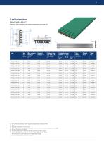
5- and 6-pole sections Standard length 4 and 6 m (6) Installation: lateral Installation: horizontal left side Voltage drop per 100 m at full rating V right side Conductor cross section (4) / mm2 Conductor material Attention: Joint material to be ordered separately (see page 10). VKS 5 eliminates conductor number 6; plastic housing however identical to VKS 6. 80 % ED Section is superseded 6 mm at 20°C UT. Same cross section at PE (ground) when used for control line. Other conductor combinations are possible. Not with UL-approval; UUL= 600 V For supply lengths above 4 m refer to restricted ambient...
Open the catalog to page 9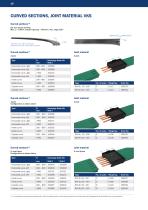
CURVED SECTIONS, JOINT MATERIAL VKS Curved sections (1) per your layout drawing Max. L = 3.60 m, support spacing: ~ 500 mm, max. angle 180° Inside curve: R Horizontal curve, right = web outside Horizontal curve, left = web inside (not shown) Joint material Horizontal curve, right Horizontal curve, left Horizontal curve, right Horizontal curve, left Inside curve Inside curve Outside curve Outside curve Joint material 4-pole Configuration as shown above Horizontal curve, right Horizontal curve, left Horizontal curve, right Horizontal curve, left Inside curve Inside curve Outside curve Outside curve...
Open the catalog to page 10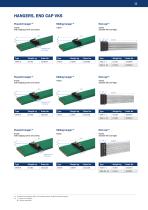
HANGERS, END CAP VKS Fixpoint hanger (1) 3-pole with tapping screw and clamp 3-pole suitable left and right tapping screw and clamp 4-pole with tapping screw and clamp 4-pole suitable left and right tapping screw and clamp 6-pole with tapping screw and clamp 6-pole suitable left and right M6 tapping screw and clamp (1) Complete with hardware (bolts, nuts, spring washers). Support spacing see page 7. (2) L = loose; c/w hardware M = Factory assembled
Open the catalog to page 11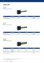
3-pole Terminal box with terminal clamps 4-pole Terminal box with terminal clamps 5- and 6-pole Terminal box with terminal clamps (1) End feeds loose as components. Sections are to be ordered separately (see page 8). (2) Cable gland ST - M40 x 1,5 for Ø = 19–28 mm ST - M20 x 1,5 for Ø = 7–13 mm Terminal cross section
Open the catalog to page 12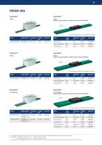
FEEDS VKS Line feed (1) 3-pole without cable connection; cable by others terminal bolt M 6 Connecting cable have to be provided by customer 4-pole without cable connection; cable by others terminal bolt M 6 Connecting cable have to be provided by customer. 5- and 6-pole without cable connection; cable by others terminal bolt M 6 Connecting cable have to be provided by customer. (1) Line feeds will be normaly installed on 1 m sections. This sections have to be ordered seperatly. (see page 8). Connecting cable by customer. (2) Cable gland STR - M63 x 1,5 for Ø= 28–45 mm Cable connection main: M10...
Open the catalog to page 13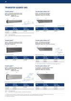
TRANSFER GUIDES VKS Transfer guides (1) Transfer guide oblique cut (1) 3-pole – for transfers, switches, spur lines Max. horizontal and vertical offset: ±2 mm Application: – straight cuts – oblique cuts, lateral 3-pole – for switches and turntables prepared per your layout drawings Application: oblique cuts, horizontal Photo shows left version Conductor system Photo shows left version Order No. Left version Order No. Right version Order No. Left version Order No. Right version Typ M: factory assembled; Typ L: (2) loose delivery as a single component, complete with accessories Transfer guide oblique...
Open the catalog to page 14All VAHLE catalogs and technical brochures
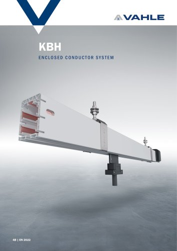 Enclosed conductor system KBH
36 Pages
 spring-operated cable reels
40 Pages
 APOS Magnetic (gliding)
2 Pages
 APOS Optic
12 Pages
 Motor powered cable reels
24 Pages
 APOS Magnetic (touchless)
8 Pages
 SMGM
SMGM20 Pages
 SMGX
SMGX20 Pages
 CPS 20kHz
24 Pages
 Charging contacts
8 Pages
 CPS 140kHz
32 Pages
 Compact conductor system VKS10
28 Pages
 Shuttle Charging System
2 Pages
 Compact conductor system VCL
8 Pages
 Insulated conductor system U10
28 Pages
 Product Portfolio
16 Pages
 Open conductor system
48 Pages
 Festoon system
28 Pages
 Enclosed conductor system MKH
40 Pages


- Analysis software solution
- Fixed reel
- Monitoring software solution
- Battery charger
- Retractable reel
- Visualization software solution
- Cable reel
- Motorized reel
- Positioner
- Mobile reel
- Electric vehicle battery charger
- Festoon system
- Electric positioner
- Smart battery charger
- Metal cable trolley
- Floor-standing battery charger
- Linear positioner
- ISO battery charger
- Forklift truck battery charger