VL
1 /92Pages

VL
1 /92Pages
Catalog excerpts

INDUSTRIAL CONTROL GENERAL PURPOSE INDUCTIVE PROXIMITY SENSORS SERIES
Open the catalog to page 1
Machine Vision ■ Industrial Automation ■ Safety V5 Group inductive sensors lines: • AC DC Inductive Proximity Sensors • DC High Voltage Inductive Proximity Sensors • DC Inductive Proximity Sensors • DC Mini-Shorter Inductive Proximity Sensors • DC Ultra-Mini Inductive Proximity Sensors • Namur Inductive Proximity Sensors • High Pressure Inductive Proximity Sensors • High Temperature Inductive Proximity Sensors Page | 2 PROXIMITY SENSORS | GENERAL PURPOSE INDUCTIVE SENSORS
Open the catalog to page 2
SELECTION GUIDE Robust sensor design for industrial applications, our inductive proximity sensors stand out due to their robustness and reliability under harsh conditions. As they provide high signal quality, temperature stability, resistance to shocks and vibrations as well as immunity to dirt and humidity, these sensors was designed to use high list of industrial applications were high stability tasks require.
Open the catalog to page 3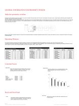
Inductive Proximity Switches operate by using an L/C resonant oscillator which generates, with the aid of a coil located in the open pot core, a high frequency alternating electromagnetic field. This field emerges from the active of the switch. When an electrically conductive material (for example a steel plate) move into the electromagnetic field, an induced edd current occurs. This eddy current extracts energy from the L/C resonant circuit in the switch, and produces a reduction in the oscillation amplitude. This reduction in the amplitude is convertedbythe associated electronic circuitry into...
Open the catalog to page 4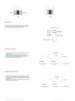
Hystresis Moving Direction HYSTERESIS is the travel of the target between the “switch on” point and the point This distance is required to allow the switch to properly detect the target and reduces the possiblity of false trips Trigger Curves Proximity Switch Leakage Current A leakage current flows through the proximity switches even when the output is turned off. Because of this the voltage remaining in the load may result in accidental operation or chattering, depending upon the load. If this occurs, connect a bleeder resister parallel to the load in order to decrease the residual voltage across...
Open the catalog to page 5
Mounting for Normal Operating Distance Because of possible interference of the electromagnetic fields generated by the oscillators, minimum spacing is required between adjacent or opposing “Active Surfaces” of proximity swithces. SHIELDED MOUNTING: The “Active Surface” may be flush with the matal in which the switch is mounted see figure “Shilded Mounting” NON SHIELDED MOUNTING: The “Active Surface” must have a free zone in which no metal is present, see figure “Non Shilded Mounting” OPPOSITE MOUNTING : When mounting proximity switches in this manner where the are opposite each other, there must...
Open the catalog to page 6
PARALLEL WIRING-"OR* FUNCTION 10-30VDC Blue Output signal Output signal Output signal mCONNECT ON SERIES WIRING -“AND' FUNCTIONPARALLEL WIRING-"OR'FUNCTION Output signal Output signal Output signal Output signal Output signal Output signal Logic functions with DC proximity sensors: Self-contained proximity sensors can be wired of four sensors with NPN and PNP outputs. T ake into account the accumulating voltage drop per sensor added in the series-string. N.O. Sensors: AND Function (all sensors made: Load “on”) N.C. Sensors: NOR Function (any one sensors open: Load “off”) Page | 7 PROXIMITY SENSORS...
Open the catalog to page 7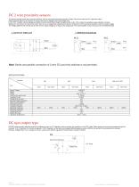
DC 2 wire proximity sensors The devices operate exactly like mechanical swithces, with the connected load beings witched in series.They can be used into PLC inputs like relays. Notice should be taken on the influence of mimum load current, leakage current and voltage drop. In the “OFF” condition, only the leakage current(the no load current) flows through the external load. In the “ON” condition the amplifiers output transistor conducts. Between the connections of the proximity switch there is now a voltage drop created by the internal Z-diode(<6V) and this should be allowed for within the supply...
Open the catalog to page 8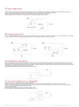
DC pnp output type DC PNP output type proximity switches are designed with the following output circuit. In N.O. Operation without sensing status, the transistor is in the OFF mode, with sensing status the transistor is in the ON mode, as the load current passes through the transistor; In the N.C. Mode, the operation is opposite in the N.O. Operation. As the load current passes 200mA(capacitive proximtiy switch over 300mA), the load short circuit protection circuit is activated Remarks: Voltage Drop<1.5V is tested in the max. Load current, 200mA, Capacitive Proximity Switch is tested in 300mA....
Open the catalog to page 9
These proximity switches are used as pilot devices for AC-operated loads such as relays, contactors, solenoids,etc. The solid state output permits the use of the proximity switches di rectly on the line in series with an appropriate load. They therefore replace mechanical limit switches without alteration of circuitry, where operating speed or environmental conditions requires the application of solid state proximity switches. These proximity switches are typically available in a voltage range of 20-250V AC or DC. All models are available with either normally open(N.O) normally closed(N.C.),...
Open the catalog to page 10
PTC SHORT CIRCUIT PROTECTION When a short occurs, a PTC in series with the switching transistor and the load gets hot and takes on a resistance value tens of times greater than normal. This prevents the switch from operating. As soon as the short is removed and the protection circuit cools, the switch is fully operation again. This kind of proximtiy switch’s voltage drop is <3V. PULSING SHORT CIRCUIT PROTECTION In case of overload or short circuit, the output transistor is rapidly switched on and off. This tests whether the short has been removed or not. This kind of proximtiy switch’s voltage...
Open the catalog to page 11
Glosary of proximity sensors terms • Sensing Distance -The physically measured distance from a particular sensor to a particular target. The three specific definitions of sensing distance are: Effective Sensing Distance(Sr) - The operating range of a sensor measured at nominal voltage and temperature. Norminal Sensing Distance(Sn)- The distance at which a sensor is designed to detect a standard target at rated voltage and temperature. Usable Sensing Distance(Su)- The distance at which a particular sensor should sense a standard target over the operating temperature and voltage limits recommonded...
Open the catalog to page 12All V5 Group catalogs and technical brochures
 VC-EZ72-V1P2-00A
6 Pages
 VC-EM36-NIP5-00
6 Pages
 V5 Brochure product
13 Pages
 8"Rugged Tablet
5 Pages
 M12
M1212 Pages
 VLQ18
VLQ188 Pages
 Machine Vision
3 Pages
 safety products catalog
8 Pages


- Copper rec visible camera
- Infrared imager
- Copper rec full-color camera
- Touch screen tablet
- Wireless tablet
- Rugged tablet
- Copper rec image processing camera
- Cylindrical proximity sensor
- Copper rec GigE camera
- Bluetooth tablet
- Thermographic camera
- GNSS tablet
- Photoelectric sensor
- IP67 proximity sensor
- Copper rec rugged video camera
- Windows tablet
- GPS tablet
- Copper rec high-speed camera