


RFnivo® 8000
RFnivo® 8000
Installation, maintenance, and commissioning of the RF 8000 should be performed by qualified personnel. The product is intended for industrial use and may cause interference in residential areas. Attention is required to prevent electric shock and material damage.
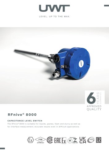
The RF 8000 is designed for level detection and pump control in various applications, including liquids, solids, slurries, and foam. It detects changes in capacitance and is available in standard and digital models. Key features include high chemical resistance, an integrated local user interface, and PROFIBUS PA communication.
Dimensions: Specific dimensions are provided for rod and rope versions, with threaded and flanged process connections.
Electrical Data: Supports a power supply of 12 to 250 V AC/DC with a repeatability of ±2 mm for conductive fluids. Includes a local user interface and supports PROFIBUS PA communication.
Mechanical Data: Constructed from powder-coated aluminum with optional stainless steel components, designed for high tensile strength.
Detailed instructions emphasize proper grounding and adherence to safety standards.
The RF 8000 can be configured locally or remotely, includes alarm signaling for fault detection, and supports standalone and networked operation.
Designed for use in hazardous areas with appropriate safety barriers and approvals.
Guidelines for probe modifications and proper disposal are provided.
- Available in threaded and welded flange versions with various sizes and materials, including ceramic isolators.
- Active shield lengths vary with standard and extended options.
- Operating conditions include a minimum relative dielectric constant of 1.5, temperature ranges from -40°C to 400°C, and pressure from -1 to 35 bar.
- Suitable for indoor and outdoor locations, with a maximum altitude of 2,000 meters.
- Ambient temperature ranges from -40°C to 85°C, with specific conditions for Ex approval.
- Installation categories and pollution degrees are specified for electronic modules.
- Detailed curves for extended rod and rope versions indicate permitted operating pressures and temperatures.
- Includes CE, UKCA, CSA, FM, TR-CU, ATEX, UKEX, INMETRO, and CCC certifications for various safety and explosion-proof standards.
- Not subject to the Pressure Equipment Directive as it lacks pressure-bearing housings.
- Features like glass windows, LED signal lamps, and various plug types are available, with specific conditions for hazardous locations.
- Recommendations for sun shielding and avoiding strong vibrations.
- Specific mounting configurations for high and low-level alarms, with spacing requirements to prevent interference.
- Warnings and guidelines for installations in potentially explosive atmospheres.
- Details on power supply requirements, relay and solid-state switch specifications, and grounding procedures.
- General and additional safety instructions for hazardous locations, emphasizing proper installation and operation by qualified personnel.
Emphasizes the use of Profibus PA standards for wiring. If not used, a shielded cable is recommended for stable measurement.
Power supply requirements are 12 to 30 V DC with a current of 12.5 mA. For intrinsically safe applications, the voltage range is 12 to 24 V DC. An intrinsically safe barrier is required for various certifications.
The solid state switch can handle 30 V DC or AC (peak) with a current of 82 mA. Intrinsically safe barriers are required for certain certifications.
Instructions for connecting the protective earth wire and using crimp type cable sockets.
Details settings for delay, failsafe high/low, test mode, and sensitivity using DIP switches and potentiometers.
Guidelines for adjusting the switchpoint based on the application, involving setting sensitivity and using potentiometers.
Common issues and solutions, such as checking power supply voltage and adjusting sensitivity and trip point potentiometers.
Instructions for use and assembly in hazardous locations, referencing relevant standards and certifications.
Specifies permitted zones for installation with markings for dust and gas applications, providing details on ATEX/UKEX Ex-Marking.
Technical information and instructions for the RF 8000, focusing on use in hazardous locations, including specifications, installation procedures, safety warnings, and disposal instructions.
Outlines various versions of the RF 8000 series, including Dust Ignition Proof, Flameproof, and Intrinsically Safe models.
Guidelines include avoiding electrostatic charge build-up, impact or friction in explosive atmospheres, and adhering to specific temperature and pressure conditions.
Emphasizes using certified cable entry devices, maintaining proper ingress protection, and ensuring chemical resistance.
Tables provide ambient and process temperature ranges, maximum surface temperatures, and temperature classes for different versions.
Instructions for shortening the rope or rod versions of the probe, with caution to avoid damaging the PFA coating.
The product is composed of recyclable materials, and recycling should be conducted by specialized companies.
Catalog excerpts
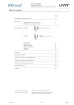
Level limit switch Series RF 8000 Technical Information / Instruction manual 2 Page Safety Notes / Technical support 2 ----------------------------------------------------------------------------------------------------Introducion Applications / Function / Features 3 Profibus System Implementation 4 ----------------------------------------------------------------------------------------------------Technical data 5 Dimensions 5 Electrical data 9 Mechanical data 11 Operating conditions 12 Approvals 16 Options 18 ----------------------------------------------------------------------------------------------------Mounting 19 ----------------------------------------------------------------------------------------------------Electrical installation 22 ----------------------------------------------------------------------------------------------------Operation - Electronic module: Standard 26 ----------------------------------------------------------------------------------------------------Operation - Electronic module: Digital 32 ----------------------------------------------------------------------------------------------------Notes for use in Hazardous Locations 33 ----------------------------------------------------------------------------------------------------Probe Modifications 38 ----------------------------------------------------------------------------------------------------Disposal 39 Subject to technical change. We assume no liability for typing errors. Different variations than specified are possible. Please contact our technical consultants.
Open the catalog to page 1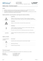
Level limit switch Series RF 8000 Technical Information / Instruction manual Safety notes / Technical support Installation, maintenance and commissioning may be accomplished only by qualified technical personnel. The product must be used only in the manner outlined in this instruction manual. This product is intended for use in industrial areas. Operation of this equipment in a residential area may cause interference to several frequency based communications. Special attention must be paid to warnings and notes as follows: WARNING Relates to a caution symbol on the product: A failure to observe...
Open the catalog to page 2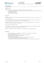
Level limit switch Series RF 8000 Technical Information / Instruction manual Applications RF 8000 is designed for level detection and simple pump control in a variety of applications: • Liquids, solids (powder and granules), slurries, interface detection (for example, oil/ water), and foam detection • Foods and pharmaceuticals • Chemical and petrochemical • High pressure and temperature Function RF 8000 is a versatile capacitance switch, ideal for level detection of interfaces, solids, liquids, slurries, and foam, and for simple pump control. The switch responds to the presence of any material...
Open the catalog to page 3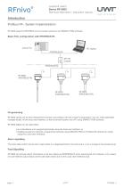
Level limit switch Series RF 8000 Technical Information / Instruction manual Profibus PA - System Implementation RF 8000 supports PROFIBUS communication protocol, and SIMATIC PDM software. Basic PLC configuration with PROFIBUS PA PDM active PLC RF 8000 carries out its level measurement function according to the set of built-in parameters. You can make parameter changes locally via the local user interface, or from a remote location via a PC using SIMATIC PDM software. RF 8000 Digital can be used either: • as a standalone unit, programmed locally using the local user interface, or • installed...
Open the catalog to page 4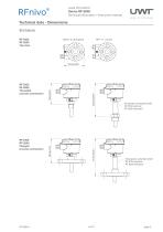
Level limit switch Series RF 8000 Technical Information / Instruction manual Technical data - Dimensions RF 8100 RF 8200 Threaded process connection Temperatur extended shaft: RF 8100 optional RF 8200 standard RF 8100 RF 8200 Flanged process connection Temperatur extended shaft: RF 8100 optional RF 8200 standard
Open the catalog to page 5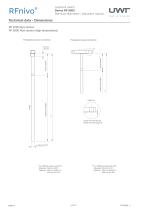
Level limit switch Series RF 8000 Technical Information / Instruction manual Technical data - Dimensions RF 8100 Rod version RF 8200 Rod version (high temperature) Threaded process connection Flanged process connection measuring length active shield active shield measuring length L does not include any raised face (see page 8) For RF8100 coated with PFA Standard 105 mm (4.13") Optional 230 mm (9,06") or 380 mm (14,96") For RF8100 coated with PFA Standard 125mm (4.92") Optional 250 mm (9.84") or 400 mm (15.75")
Open the catalog to page 6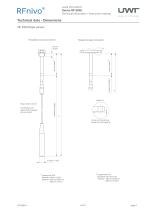
Level limit switch Series RF 8000 Technical Information / Instruction manual Technical data - Dimensions Threaded process connection Flanged process connection measuring length active shield active shield For RF8100 with optional PFA coating: ø10mm (0.36") measuring length L does not include any raised face (see page 8) Coated with PFA Standard 105 mm (4.13") Optional 230 mm (9,06") or 380 mm (14,96") Coated with PFA Standard 125mm (4.92") Optional 250 mm (9.84") or 400 mm (15.75")
Open the catalog to page 7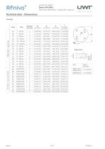
Level limit switch Series RF 8000 Technical Information / Instruction manual Technical data - Dimensions Flanges ASME B16.5, raised face EN 1092-1 type A, flat faced Raised face facing thickness Facing thickness
Open the catalog to page 8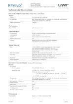
Level limit switch Series RF 8000 Technical Information / Instruction manual Technical data - Electrical data Electronic module: Standard (Relay SPDT / Solid State) Power Supply Max. voltage which does not invalidate the intrinsically safe protection of the sensor (probe): Um = 250V AC Power consumption Performance Repeatability User Interface Configuration Locally, using dip switches and potentiometers Local display Relay contact and solid-state switch Relay and solid-state switch can be de-energized in the absence of a sensor signal Signal Outputs Relay 1 Form C (SPDT) contact (selectable NC...
Open the catalog to page 9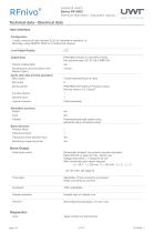
Level limit switch Series RF 8000 Technical Information / Instruction manual Technical data - Electrical data User Interface Configuration Locally, using local user interface (LUI), for standalone operation, or Remotely, using SIMATIC PDM on a Profibus PA network Local Digital Display PROFIBUS PA (IEC 61158 CPF3 CP3/2) Bus physical layer: IEC 61158-2 MBP(-IS) Polarity-independent Simultaneous communication with Master Class 2 Cyclic User data (normal operation) Byte output 2 bytes representing one value Byte input Device profile PROFIBUS PA Profile for Process Control Devices Version 3.0, Class...
Open the catalog to page 10All UWT GmbH catalogs and technical brochures
 Brochure Chemical Industry
21 Pages
 Capanivo® 7000
2 Pages
 SOLUTIONS FOR THE FOOD INDUSTRY
21 Pages
 Product-Overview UWT
36 Pages
 Vibrasil 70/90
2 Pages
 DK value
8 Pages
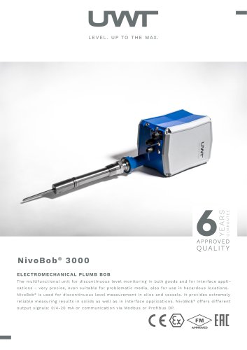 NivoBob® NB 3000
2 Pages
 Product Matrix
2 Pages
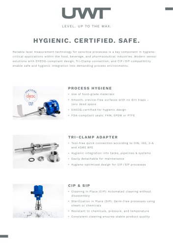 Hygiene-Flyer-EHEDG
2 Pages
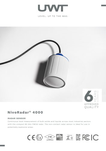 NivoRadar® NR 4000
2 Pages
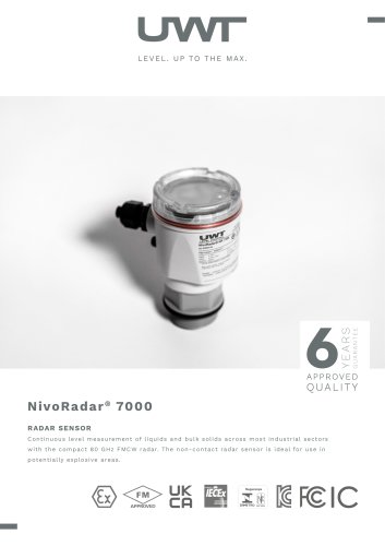 NivoRadar® NR 7000
2 Pages
 NivoRadar® NR 3000
2 Pages
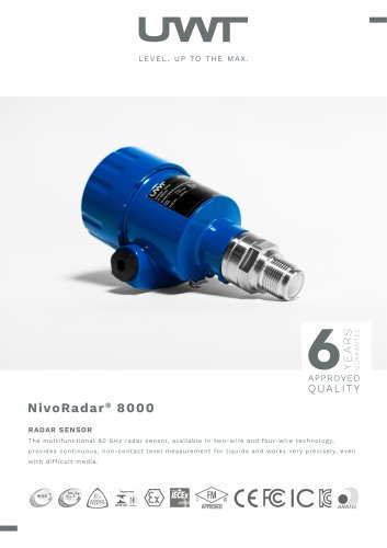 NivoRadar® NR 8000
2 Pages
 Capanivo® CN 4000
22 Pages
 Capanivo® CN 7000
50 Pages
 Capanivo® CN 8000
42 Pages
 Mononivo® 4000
25 Pages
 NivoBob® 3000
41 Pages
 NivoCapa® 8000
27 Pages
 NivoBob® 4000
31 Pages
 NivoGuide® NG 8000
84 Pages
 NivoTec® NT 4700
7 Pages
 NivoTec® NT 4500
20 Pages
 RFnivo® 3000
44 Pages
 Rotonivo® 4000
21 Pages
 Radar Flyer New 2024
2 Pages
 Vibranivo® VN 4000
25 Pages
 Solids - Liquids at a glance
2 Pages
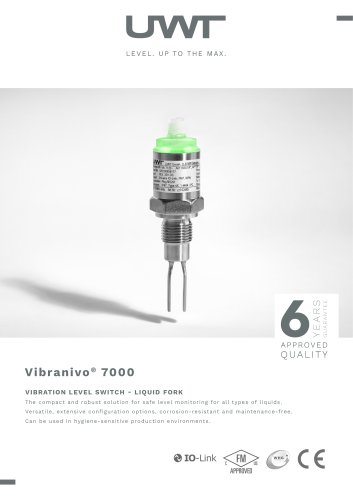 Vibranivo® VN 7000
2 Pages
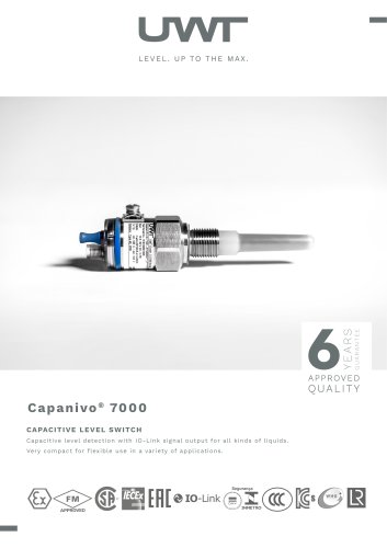 Capanivo® CN 7000
2 Pages
 NivoCapa® NC 8000
2 Pages
 Vibranivo® VN 4000
2 Pages
 RFnivo® 8000
2 Pages
 Rotonivo® RN 4000
2 Pages
 RFnivo® 3000
2 Pages
 Rotonivo® RN 3000 / 6000
2 Pages
 NivoGuide® NG 3000
2 Pages
 NivoGuide® NG 8000
2 Pages
 NivoBob® NB 4000
2 Pages
 Mononivo® MN 4000
2 Pages
 Capanivo® CN 4000
2 Pages
 Capanivo® CN 8000
2 Pages



Archived catalogs

- UWT level switch
- UWT liquid level switch
- UWT level sensor
- UWT liquid level sensor
- Warning light
- UWT analog level sensor
- LED beacon light
- DC beacon light
- UWT stainless steel level switch
- Level transmitter
- Liquid level transmitter
- UWT digital output level sensor
- AC warning light
- UWT threaded level switch
- UWT storage tank level sensor
- Analog level transmitter
- Liquids level gauge
- Tank level limit switch
- Steady warning light
- Plastic level switch