


NivoCapa® 8000
NivoCapa® 8000
- Installation, maintenance, and commissioning should be conducted by qualified personnel only.
- The product is intended for industrial use and may interfere with residential areas.
- Warnings highlight potential risks of death, serious injury, or material damage.
- Contact UWT GmbH for technical support.
- The NC 8000 is designed for level measurement in industries such as food, pharmaceuticals, and chemicals.
- It functions in liquids, bulk solids, and slurries, even in challenging environments.
- Features include corrosion-resistant construction, adjustable range, and proven technology.
- Dimensions: Available in rod and rope versions with threaded and flanged connections.
- Electrical Data: Operates on 12-30 V DC, with a 4-20 mA current loop signal.
- Mechanical Data: Constructed with stainless steel and PFA, suitable for various process connections.
- Operating Conditions: Pressure range from -1 to 35 bar, temperature range from -40 to 200°C.
- Certified for general purpose, dust ignition proof, flame proof, and marine applications.
- Complies with CE, UKEX, CSA, FM, and other international standards.
- Installation should comply with local regulations and be performed by qualified personnel.
- Ensure materials are compatible with the specific environment.
- Includes safety barriers for hazardous areas and diagnostics for system monitoring.
- Rope probes can be shortened as needed.
- Follow proper disposal procedures for electronic equipment.
- Ensure chemical compatibility of materials before installation.
- Select appropriate bolting and gasket materials suitable for service conditions.
- Follow grounding procedures to prevent electrostatic shock.
- Ensure matching threads before inserting the instrument to avoid damage.
- Cable entry devices must withstand temperatures from -40°C to 10 K above max ambient temperature.
- Do not disassemble connections under pressure.
- Use PTFE tape or appropriate sealing compounds for pressure applications.
- NC 8000 units comply with ASME and European Pressure Equipment Directive standards.
- Do not exceed a tensile strength of 1900 kg/4188 lbs.
- Ensure the load capacity of the silo/tank roof can withstand the force on the rope.
- Handle units with rods longer than 2 m carefully to prevent damage.
- Support the NC 8000 at specified points when lifting from a horizontal position.
- The rope version is designed for top mounting and should be used according to the material's conductivity.
- Power supply: 12 to 30 V DC, 2-wire current loop 4-20mA.
- Use shielded cables for stable measurement.
- Follow specific wiring instructions for hazardous locations.
- The user interface includes an LCD, rotary switch, and push-buttons.
- Menu positions allow for setting range values, fault protection, and diagnostics.
- Damping values can be adjusted to alter the delay in measurement response.
- NC 8000 requires no regular maintenance.
- Repairs should be conducted by qualified personnel using manufacturer-provided components.
- Recommission the NC 8000 when replacing transmitters or probes, following the start-up procedure.
The document provides technical information and instructions for the NivoCapa® NC 8000 continuous level measuring system, focusing on its use in hazardous locations. It includes specifications, procedures, standards, and recommendations for installation, operation, and maintenance.
The NC 8000 system is designed for continuous level measurement and is suitable for use in hazardous environments as per ATEX Directive 2014_34_EU and INMETRO standards. It is not assessed as a safety-related device. The equipment is marked with specific codes indicating its compliance with ATEX and UKEX certifications.
The document outlines the procedure for setting the Upper Range Value (URV) for level measurement. It includes steps for adjusting the rotary switch and calculating the URV based on actual measurements. The best results are achieved using the highest possible actual level.
Installation and inspection must be performed by trained personnel following applicable codes of practice. The document emphasizes the importance of turning off power before servicing and provides guidelines for handling process pressure and material during removal.
The document details the permitted zones for installation, marking requirements, and specific conditions of use in hazardous locations. It includes information on electrostatic charge prevention, flameproof joints, and temperature ranges.
Users must ensure the equipment is not exposed to conditions causing electrostatic charge buildup. The document provides warnings for installation, including cable entry devices and blanking elements, and emphasizes the need for certified components.
The document specifies ambient and process temperature ranges, maximum surface temperatures, and temperature classes. It highlights the limitations of ATEX approvals concerning atmospheric pressure and provides guidance for assessing deviating pressure conditions.
Instructions for shortening the rope version of the probe are provided, along with disposal guidelines. The document advises on the use of appropriate tools and techniques to ensure proper assembly and recycling of materials.
Catalog excerpts
Continuous level measuring system NC 8000 Technical information / Instruction manual 2 Page Safety Notes / Technical support 2 ----------------------------------------------------------------------------------------------------Introducion Applications / Function / Features 3 ----------------------------------------------------------------------------------------------------- Dimensions 4 Electrical data 8 Mechanical data 9 Operating conditions 10 Approvals 13 ----------------------------------------------------------------------------------------------------Mounting 14 ----------------------------------------------------------------------------------------------------Electrical installation 16 ----------------------------------------------------------------------------------------------------Operation 17 ----------------------------------------------------------------------------------------------------Notes for use in Hazardous Locations 22 ----------------------------------------------------------------------------------------------------Probe Modifications Shortening the rope (rope version) 27 ----------------------------------------------------------------------------------------------------Disposal 27 Subject to technical change. We assume no liability for typing errors. Different variations than specified are possible. Please contact our technical consultants.
Open the catalog to page 1
Continuous level measuring system NC 8000 Technical information / Instruction manual Safety notes / Technical support Installation, maintenance and commissioning may be accomplished only by qualified technical personnel. The product must be used only in the manner outlined in this instruction manual. This product is intended for use in industrial areas. Operation of this equipment in a residential area may cause interference to several frequency based communications. Special attention must be paid to warnings and notes as follows: WARNING Relates to a caution symbol on the product: A failure...
Open the catalog to page 2
Continuous level measuring system NC 8000 Technical information / Instruction manual Applications NC 8000 is a cost-effective instrument for level measurement in applications such as the processing of food and beverages, pharmaceuticals, detergents and pet food. It performs in liquids, bulk solids and slurries, including viscous (conductive or nonconductive) materials, even in challenging environments involving vapour and dust. • Mining and cement • Power • Food and beverage • Water • Chemical • Oil and gas 4 Function NC 8000 is a 2-wire instrument combining a sophisticated, yet easy-to-adjust,...
Open the catalog to page 3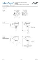
Continuous level measuring system NC 8000 Technical information / Instruction manual Technical data - Dimensions NC 8100 Threaded process connection Temperatur extended shaft NC 8100 Flanged process connection Temperatur extended shaft
Open the catalog to page 4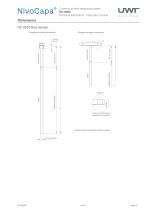
Continuous level measuring system NC 8000 Technical information / Instruction manual NC 8100 Rod version Threaded process connection Flanged process connection active shield measuring length L does not include any raised face (see page 7) Active shield and probe is PFA coated
Open the catalog to page 5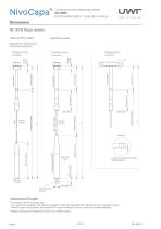
Continuous level measuring system NC 8000 Technical information / Instruction manual NC 8100 Rope version Rope not PFA coated Applicable for isolating (non conductive) media only Threaded process connection Flanged process connection Threaded process connection active shield see note 2 measuring length measuring length measuring length active shield active shield L does not include any raised face(see page 7) stainless steel weight Active shield is PFA coated ² For version with PFA coated rope: For conductive materials, the measuring length includes the exposed PFA coated rope only. Any fluid...
Open the catalog to page 6
Continuous level measuring system NC 8000 Technical information / Instruction manual EN 1092-1 type A, flat faced facing thickness ASME B16.5, raised face Facing thickness
Open the catalog to page 7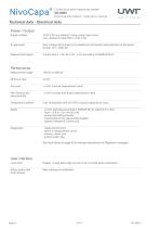
Continuous level measuring system NC 8000 Technical information / Instruction manual Technical data - Electrical data Power / Output Supply voltage 12-30 V DC any polarity, 2-wire current loop circuit, max. resistance value 550 Ω @ 24 V DC Max. voltage which does not invalidate the intrinsically safe protection of the sensor (probe): Um = 250V AC Measurement signal Current loop 4 – 20 mA or 20 – 4 mA according to NAMUR NE 43 Performance Measurement range Minimum span < 0.5% of actual measurement value < 0.4% full scale and actual measurement value Temperature stability max. temperature drift...
Open the catalog to page 8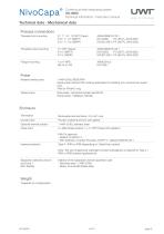
Continuous level measuring system NC 8000 Technical information / Instruction manual Technical data - Mechanical data Process connections Threaded rod mounting ¾", 1", 1¼", 1½"NPT (Taper) R ¾", 1", 1½" (BSPT) G ¾", 1", 1½" (BSPP) ANSI/ASME B1.20.1 EN 10226; PT (JIS-T), JIS B 0203 EN ISO 228-1; PF (JIS-P), JIS B 0202 Threaded rope mounting 1½" NPT (Taper) R 1½" (BSPT) G 1½" (BSPP) ANSI/ASME B1.20.1 EN 10226; PT (JIS-T), JIS B 0203 EN ISO 228-1; PF (JIS-P), JIS B 0202 Flange mounting Probe Material wettet parts 1.4404 (316L)/PEEK/PFA Rope probe without PFA coating applicable for isolating (non...
Open the catalog to page 9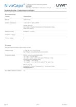
Continuous level measuring system NC 8000 Technical information / Instruction manual Technical data - Operating conditions Environmental Location Ambient temperature – 40 to +85°C (– 40 to +185°F) With Ex approval: Depending on Surface Temperature and Temperature Class, details see page 26. Relative humidity Installation category Pollution degree Note: Not recommended for direct steam contact Pressure range -1 to 35 bar g (-14.6 to 511 psi g) See Pressure versus temperature curves below Temperature range Without temperature extended shaft: –40 to 85°C (–40 to 185°F) –20 to 85°C (–4 to +185°F)...
Open the catalog to page 10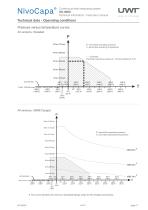
Continuous level measuring system NC 8000 Technical information / Instruction manual Technical data - Operating conditions Pressure versus temperature curves All versions, threaded P= permitted operating pressure T= permitted operating temperature ---- Example: Permitted operating pressure = 30 bar (435psi) at 75°C All versions, ASME flanged P= permitted operating pressure T= permitted operating temperature 11 1) The curve denotes the minimum allowable flange class for the shaded area below.
Open the catalog to page 11All UWT GmbH catalogs and technical brochures
 Brochure Chemical Industry
21 Pages
 Capanivo® 7000
2 Pages
 SOLUTIONS FOR THE FOOD INDUSTRY
21 Pages
 Product-Overview UWT
36 Pages
 Vibrasil 70/90
2 Pages
 DK value
8 Pages
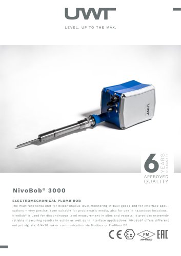 NivoBob® NB 3000
2 Pages
 Product Matrix
2 Pages
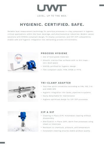 Hygiene-Flyer-EHEDG
2 Pages
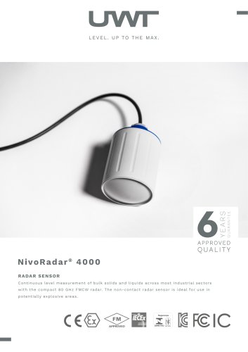 NivoRadar® NR 4000
2 Pages
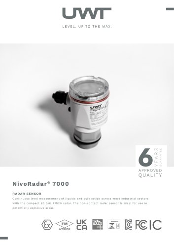 NivoRadar® NR 7000
2 Pages
 NivoRadar® NR 3000
2 Pages
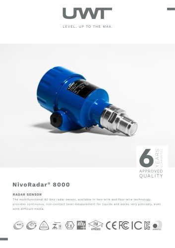 NivoRadar® NR 8000
2 Pages
 Capanivo® CN 4000
22 Pages
 Capanivo® CN 7000
50 Pages
 Capanivo® CN 8000
42 Pages
 Mononivo® 4000
25 Pages
 NivoBob® 3000
41 Pages
 NivoBob® 4000
31 Pages
 NivoGuide® NG 8000
84 Pages
 NivoTec® NT 4700
7 Pages
 NivoTec® NT 4500
20 Pages
 RFnivo® 3000
44 Pages
 RFnivo® 8000
39 Pages
 Rotonivo® 4000
21 Pages
 Radar Flyer New 2024
2 Pages
 Vibranivo® VN 4000
25 Pages
 Solids - Liquids at a glance
2 Pages
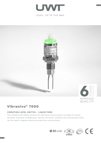 Vibranivo® VN 7000
2 Pages
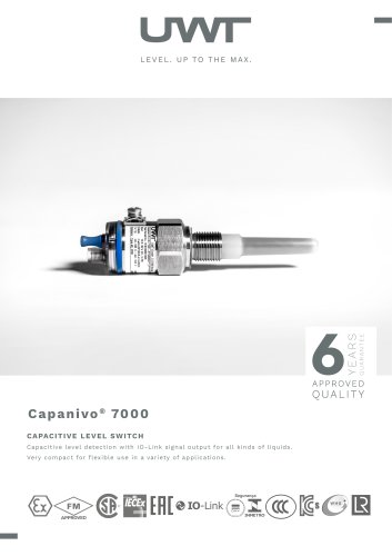 Capanivo® CN 7000
2 Pages
 NivoCapa® NC 8000
2 Pages
 Vibranivo® VN 4000
2 Pages
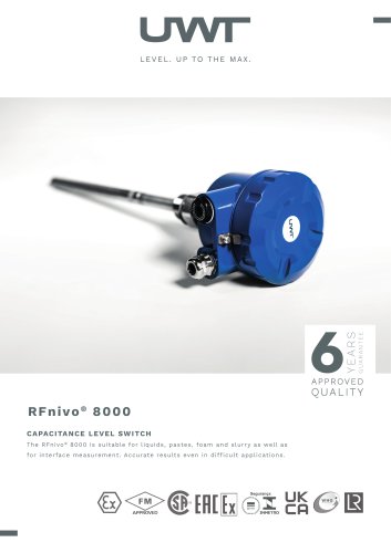 RFnivo® 8000
2 Pages
 Rotonivo® RN 4000
2 Pages
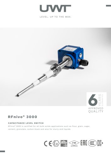 RFnivo® 3000
2 Pages
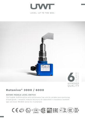 Rotonivo® RN 3000 / 6000
2 Pages
 NivoGuide® NG 3000
2 Pages
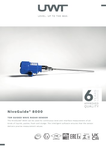 NivoGuide® NG 8000
2 Pages
 NivoBob® NB 4000
2 Pages
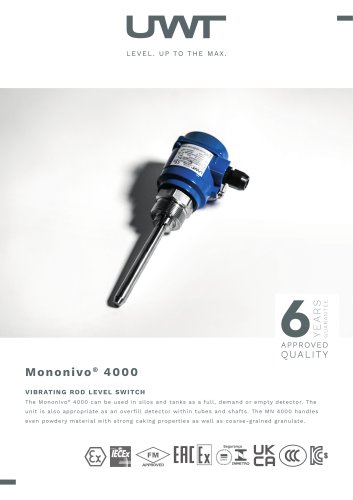 Mononivo® MN 4000
2 Pages
 Capanivo® CN 4000
2 Pages
 Capanivo® CN 8000
2 Pages



Archived catalogs

- UWT level switch
- UWT liquid level switch
- UWT level sensor
- UWT liquid level sensor
- Warning light
- UWT analog level sensor
- LED beacon light
- DC beacon light
- UWT stainless steel level switch
- Level transmitter
- Liquid level transmitter
- UWT digital output level sensor
- AC warning light
- UWT threaded level switch
- UWT storage tank level sensor
- Analog level transmitter
- Liquids level gauge
- Tank level limit switch
- Steady warning light
- Plastic level switch