- Catalogs
- Utility Solutions Inc
- FIELD INSPECTION PROCEDURE BREAK-SAFE® Load Break & Pick-up Tool
FIELD INSPECTION PROCEDURE BREAK-SAFE® Load Break & Pick-up Tool
1 /2Pages

FIELD INSPECTION PROCEDURE BREAK-SAFE® Load Break & Pick-up Tool
1 /2Pages
Catalog excerpts
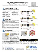
BREAK-SAFE® Load Break & Pick-up Tool I ICDO yi C 4 qq Follow the steps below before EACH use of the BREAK-SAFE®.This procedure does NOT replace or UiBS-46-2-PS eliminate the periodic maintenance that is recommended every 2 years. PATENT NO. 6,078,008 Other Patents Pending Brass Contacts VISUAL INSPECTION 0 Visually inspect the tool. If any of the following are found, remove the tool from the field and perform service: • Soot or Dirt buildup on components • Damage to contacts • Cracks of 1/4” or more on outer tube • Damaged Load Break Ring. Ring should rotate freely (shaft should NOT rotate) • Damaged or discolored Yellow Tube • Damaged Conductor Hook or Duckbill • Loose Conductor Bar • Damaged Safety Lock • Out of Date Maintenance Decal (service should be performed within 2 years of date shown) CONTINUITY The Brass Contacts do not carry the load during Load Break operation. The current path will exist inside the tool until the load break mechanism is triggered. A) With the tool in the CLOSED position, use a voltmeter, confirm continuity exists between the Conductor Bar and the Conductor Hook. B) Confirm continuity exists while pulling the Load Break Ring toward the open position. Continuity should exist until the load break mechanism is engaged and the tool locks in the open position. C) Confirm NO continuity exists between the Conductor Bar and the Conductor Hook when the tool is in the fully opened positioned. RESET TOOL The BREAK-SAFE® will only reset when the Brass Contacts are fully seated. Exert a steady downward movement on the Load Pick-up Trigger (D). The Load Break Ring Assembly should retract forcefully into the Clear Tube Assembly. The tool should operate firmly and smoothly. With the tool in the Lock Close position, confirm the Brass Contacts are fully seated (E). The Brass Contacts will fit inside one another so the fingers of the top Brass Contact are touching the lip of the lower Brass Contact. A WARNING A Carefully read and fully understand the manual prior to operating, maintaining or testing this device. Improper operation, handling or maintenance of this device can result in death, grievous personal injury and or equipment damage. The Brass Contacts should remain seated with the tool in the CLOSED position (F). Push the Load Break Ring up and into the tool to ensure the Brass Contacts are fully seated. The tool will require service and should NOT be used if the Brass Contacts cannot be fully seated. |C UTI1.ITY >“ Solutions Lineman driven. Field proven.® Web www.utilitysolutionsinc.com USBS Field Inspection (11-9-15) 101 33rd Street Drive SE • Hickory, NC 28602 Copyright © 2015 Utility Solutions, In
Open the catalog to page 1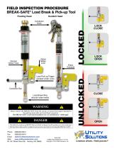
Floating Head Duckbill Head Internal Yellow Tube Conductor Hook Yellow Safety Lock Load Pick-up Trigger (located under Lock) LOCK CLOSE LOCK OPEN Brass Contacts Load Break Ring (should rotate freely) fu warning A Always remove the BREAK-SAFE' from the circuit, or remove the jumper attached to the parking stand, after each load break operation. The BREAK-SAFE* is not rated insulation nor is it considered a “visible gap”. Fk DANGER A The Safety Lock does not RESET the tool. Refer to Inspection Procedure on reverse side and the Operation Manual for complete instructions on properly resetting...
Open the catalog to page 2All Utility Solutions Inc catalogs and technical brochures
 Spline Torque Bar
2 Pages
 BLUE STRIPE® Rescue Hook
1 Page
 BLUE STRIPE® Shotgun Sticks
2 Pages
 Meter Grabber
1 Page
 Grounds Tester
1 Page
 Universal URD Wrench
1 Page


