USB4
1 /8Pages

USB4
1 /8Pages
Catalog excerpts
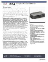
Encoder Data Acquisition USB DevicePage 1 of 8 Features Real-time tracking of up to 4 incremental encoders with or without index (up to 5 MHz encoder input frequency) 4 channel pulse width, pulse period and RPM measurement Available with single-ended or differential encoder inputs, optional DIN rail mounting 8 digital outputs, 8 digital inputs, 4 A/D inputs , 4 D/A outputs Flexible triggering modes and 32 Mbyte RAM buffer for data capture Programmable sampling period from 2 uS to approx. 2 hours Digital input levels up to +25V Digital outputs with open drain FET for up to 1A switching Easy to use demo software, Windows DLLs for C++/C#/Visual Basic and example source code provided The USB4 is a data acquisition device designed to record data from 4 incremental encoders, 8 digital inputs and 4 analog input channels. In addition, the USB4 provides 8 digital outputs and 4 analog output channels. The 8 digital outputs also have a latching emergency stop (E-Stop) input. When the E-Stop input is activated, the 8 digital outputs will turn off immediately. The analog input/output channels provide 12-bit data conversions at rates up to 44 kHz per channel. All communication between the USB4 and the host PC is sent over a USB interface. To handle continuous streaming of data over USB to the host PC, the USB4 has a 32 Mbyte FIFO buffer. The digital input port can handle input logic levels from +3V to +25V and the digital output port has open drain MOSFET outputs to switch up to 1A at +25V. The range of the analog input/output channels is 0V to +5V. Four independent incremental encoder interfaces are implemented in hardware on the USB4. Each encoder channel has a 24-bit up/down counter that is easily reconfigured for various counting modes such as modulo-N, non-recycle, range-limit and normal counter mode. Quadrature input modes ofx1, x2, x4, clock/direction, and indexing modes can be selected. Each encoder channel can measure the pulse width and pulse period of its "A" input while simultaneously decoding the quadrature state. This feature allows RPM speed measurements to be made from the encoder input or interfacing to sensors with PWM (pulse width modulated) outputs. The USB4 can capture data once per clock cycle of a user programmable 32-bit clock generator or on every rising or falling edge of the input port pins. Data capture can be programmed to run continuously or to start only when certain conditions are met such as the encoder count matching a certain value, or if the there is encoder movement in a certain direction. Encoder events can also output on the output port to trigger external devices. Trigger conditions can be set for the analog input and PWM input channels; in addition, the USB4 can be configured to have the input port pins serve as a trigger to start data acquisition. The input port triggering allows the user to form the final trigger from a combination of conditions on the input port with up to 2 levels of triggering. Software and documentation needed to use the USB4 is available on the US Digital website. A PC demo application allows the user to configure and explore various features of the USB4 using a graphical user interface. A library with a detailed Application Programming Interface is included so users can develop their own applications. US Digital provides several examples that demonstrate how to use the FIFO, how to log data, etc. For users that prefer lower level control, a documented register based interface is provided so the USB4's internal registers can be configured at the bit... DIGITAL Vancouver, Washington 98684, USA www.usdigital.com Toll-free: 800.736.0194
Open the catalog to page 1
Encoder Data Acquisition USB Device Page 2 of 8 Description (Continued) ... level. ► www.usdigital.com/support/software/usb4-software ► www.usdigital.com/assets/USDProducts.zip (.zip file with installer) Mechanical Drawing0 Environmental Parameter Min. Max. Units Parameter Value Digital Output Pins Open drain voltage, 25V max. DIGITAL Vancouver, Washington 98684, USA www.usdigital.com Toll-free: 800.736.0194
Open the catalog to page 2
DIGITAL Vancouver, Washington 98684, USA www.usdigital.com Toll-free: 800.736.0194
Open the catalog to page 3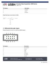
DIGITAL Vancouver, Washington 98684, USA www.usdigital.com Toll-free: 800.736.0194
Open the catalog to page 4
Encoder Data Acquisition USB Device Page 5 of 8 No connection B- channel B+ channel ^ Digital Input PortJ8 Pin-out: Pin Number 1 2 3 4 5 6 7 8 9 10 Description +5V power out Din0 (LSB) Din1 Din2 Din3 Din4 Din5 Din6 Din7 (MSB) Ground Input Port Circuit (internal to USB4): USE= 1400 NE 136th Avenue DIGITAL Vancouver, Washington 98684, USA [email protected] www.usdigital.com
Open the catalog to page 5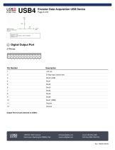
US5= I |CD>1 Encoder Data Acquisition USB Device DIGITAL UOD4 Page 6 of 8 +3-3V 100k S 10k digital input pins -►--WV + internal J8: pins 2,3.43,6,7,8,9 J7: pin 2 VIL (max) = 0.8V VIH(min) ■ 2V with approx. 100 mV hysteresis VIH(max)» 24V ® Digital Output Port J7 Pin-out: mmmm 1 2 3 4 5 6 7 8 9 10 11 12 DIGITAL Vancouver, Washington 98684, USA www.usdigital.com Toll-free: 800.736.0194
Open the catalog to page 6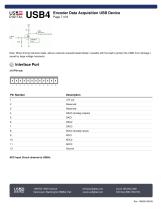
US5= I |CD>1 Encoder Data Acquisition USB Device DIGITAL UOD4 Page 7 of 8 +5V 12k < .• ., a 1 ^ output pins Note: When driving inductive loads, add an external reversed biased diode in parallel with the load to protect the USB4 from damage c aused by large voltage transients. Interface Port J10 Pin-out: 1 2 3 4 5 6 7 8 9 10 11 12 DIGITAL Vancouver, Washington 98684, USA www.usdigital.com Toll-free: 800.736.0194
Open the catalog to page 7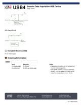
Encoder Data Acquisition USB Device Page 8 of 8 Input S =Single-ended D =Differential Mounting D =Default R =DIN rail (35mm wide) Notes ► Cables and connectors are not included and must be ordered separately. ► US Digital® warrants its products against d efects in materials and workmanship for two years. See complete warranty for details. DIGITAL Vancouver, Washington 98684, USA www.usdigital.com Toll-free: 800.736.0194
Open the catalog to page 8All US Digital catalogs and technical brochures


- Display module
- Data connector
- SARRALLE rotary encoder
- Socket electrical connector
- SARRALLE incremental rotary encoder
- SARRALLE absolute rotary encoder
- LED display panel
- SARRALLE inclinometer
- SARRALLE solid-shaft rotary encoder
- SARRALLE optical rotary encoder
- SARRALLE hollow-shaft rotary encoder
- SARRALLE magnetic rotary encoder
- Industrial rotary encoder
- Programmable display system
- Right-angle electrical connector
- SARRALLE compact rotary encoder
- SARRALLE digital inclinometer
- DC rotary encoder