- Catalogs
- US Digital
- MD3 Microstepping Motor Driver
MD3 Microstepping Motor Driver
1 /7Pages

MD3 Microstepping Motor Driver
1 /7Pages
Catalog excerpts
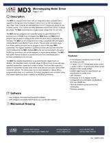
Microstepping Motor Driver Page 1 of 7 The MD3 is a stepper motor driver with an integrated motion controller that is capable of driving size 14 to 42 stepper motors from 2 to 256 microsteps per step. Peak motor currents are selectable from 0.5 to 7.0 Amps per phase for the H-option version. The L-option provides selectable current from 0.05 to 1.8 Amps per phase. The MD3 is powered by a single supply voltage from 9 to 50 VDC. The MD3 can be configured and controlled using the open MODBUS RTU protocol over an RS485 bus. US Digital's free MD3 Setup and MD3 Demo program can be used to configure and control the drive using a graphical user interface. The MD3 can be configured to be mostly compatible with US Digital's existing MD2S-D and MD2S-P motor drivers. The pre-wired connector plugs from these existing products can be plugged in as-is to the larger MD3 connectors. The register interface is published so that user can write their own control software for the MD3. Multiple MD3 units can be connected to the same RS485 bus since each unit can be assigned a unique device address. The MD3 has built-in thermal shutdown to protect the drive from overheating and is firmware updatable by the end user. The MD3 has isolated step/direction or go-stop/direction digital inputs. In addition, the integrated motion controller allows Profile and Jog moves with user-specified acceleration, speed and number of steps. The drive also supports a switch or incremental encoder index home cycle with pre- and post- home offset movement options. The Home cycle can run automatically on startup after a programmable delay or on command. All motion commands can be started using the isolated digital input lines in addition to MODBUS commands. ► 8 microstepping resolutions from 2 to 256 microsteps per step ► -H option: 0.5 to 7.0 Amps peak phase current ► -L option: 0.05 to 1.8 Amps peak phase current ► Single 9 to 50V supply voltage ► Isolated digital inputs for step/direction, go-stop/direction or profile move ► LED indicators ► Drives size 14 to 42 stepper motors ► Configurable and controllable via MODBUS RTU over RS485 bus ► Thermal shutdown protects drive from overheating ► Firmware updatable r* Software ► www.usdigital.com/support/software/md3-software ► www.usdigital.com/assets/USDProducts.zip (.zip file with installer) Mechanical Drawing USE= 1400 NE 136th Avenue [email protected] Local: 360.260.2468 DIGITAL Vancouver, Washington 98684, USA www.usdigital.com Toll-free: 800.736.0194
Open the catalog to page 1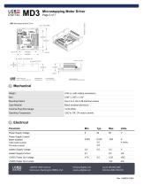
Microstepping Motor Driver Page 2 of 7 0 Electrical Parameter Min. Typ. Max. Units Power Supply Voltage Power Supply Current Motor disabled 3.5A motor current 7A motor current Isolator Supply Voltage Isolator Supply Current +5VDC Power Out Voltage +5VDC Power Out Current DIGITAL Vancouver, Washington 98684, USA www.usdigital.com Toll-free: 800.736.0194
Open the catalog to page 2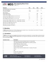
Microstepping Motor DriverPage 3 of 7 Parameter Peak Output Phase Current (selectable) High Current (H-option) Low current (L-option) Step Frequency External step/direction Internal motion controller Logic Low Input Voltage (J2 pins 2, 3, 4, 5, 9, 10, 12) Logic High Input Voltage (J2 pins 2, 3, 4, 5, 9, 10, 12) Input Leakage Current (J2 pins 2, 3, 4, 5, 9, 10, 12) Logic Low Output Voltage (J2 pins 9,10,12 - output mode), 3 mA load Logic High Output Voltage (J2 pins 9,10,12 - output mode), 2 mA load Open drain FET voltage rating (J3 pins 7,8) Open drain FET current (J3 pins 7,8) Electrostatic...
Open the catalog to page 3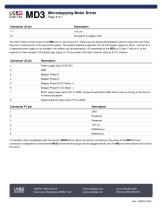
Microstepping Motor DriverPage 4 of 7 Description The main motion control inputs of the MD3 are on J2 pins 2,3,4,5. These pins are electrically isolated to prevent noise from the motor drive from crossing over to the rest of the system. The isolator requires a separate 2.5V to 5.5V power supply on J2 pin 1 and pin 6. If a separate power supply is not available, the isolator can be powered by +5V generated by the MD3 on J2 pins 7 and pin 8, at the expense of noise isolation. All isolated logic inputs on J3 are pulled to the high (inactive) state by 5 kQ resistors. 1 Power supply input, 9-50...
Open the catalog to page 4
Microstepping Motor Driver -HEARTBEAT -CURRENT CUTBACK I B/OUTO 112 k +5VOUT 111 MD3 +5V0UT 7 MICROSTEPPING ISO. + 5V 6 MOTOR DRIVER DIRECTION 5 STEP/GO-STOP 4 INHIBIT/HOME 3 LOW CURRENT / SPEED / HOME SENSOR 2 ISO. GND 1 - - LOT# Ml23456 J2 State Heartbeat LED (Green, D6) Current Cutback LED (Red, D5) Boot-up Both LED's will flash on/off twice if the MD3 registers were loaded without errors from EEPROM. If there are errors, the red LED will flash rapidly on/off for 5 seconds and the MD3 registers will be initialized with default values. The drive will then enter the "Startup...
Open the catalog to page 5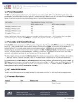
Microstepping Motor DriverPage 6 of 7 0 Power Dissipation The MD3 can safely dissipate a sufficient amount of heat in free air for motor currents of 7A or less. The following table shows some typical housing temperatures after 24 hours of continuous operationwithout any additional heat sink. The metal housing of the MD3 can be kept cooler if it is mounted to a heat sinking metal surface or if the drive is operated intermittently. Test Condition Be sure that the motor screw terminal connections on J3 are tight. Loose connections have a higher resistance which may cause excessive heating at the...
Open the catalog to page 6
Microstepping Motor Driver Page 7 of 7 Version H =High Current L =Low Current Notes ► Cables and connectors are not included and must be ordered separately. US Digital® warrants its products against defects in materials and workmanship for two years. See complete warranty for details. DIGITAL Vancouver, Washington 98684, USA www.usdigital.com Toll-free: 800.736.0194
Open the catalog to page 7All US Digital catalogs and technical brochures


- Display module
- Data connector
- Angular encoder
- Socket electrical connector
- Incremental rotary encoder
- Absolute rotary encoder
- LED display panel
- Tilt sensor
- Solid-shaft rotary encoder
- Optical rotary encoder
- Hollow-shaft rotary encoder
- Magnetic rotary encoder
- Industrial rotary encoder
- Programmable display system
- Right-angle electrical connector
- Compact rotary encoder
- Digital inclination sensor
- DC rotary encoder