
- Catalogs
- Universal Robots A/S
- Universal Robots User Manual


Universal Robots User Manual

Universal Robots User Manual
This manual provides comprehensive instructions for the installation and programming of the Universal Robots UR20. It is divided into two main parts: the Hardware Installation Manual and the PolyScope Manual. The manual is intended for integrators with basic mechanical, electrical, and programming knowledge. Additional resources and support can be found on the Universal Robots support website and through the UR+ and myUR platforms.
Safety
This section emphasizes the importance of safety and outlines the responsibilities of integrators to ensure compliance with safety standards. It includes guidelines for risk assessment, safety settings, and the importance of not modifying safety measures. Various safety message types are defined, such as warnings for hazardous situations and electrical risks.
Instructions on the proper use of round slings for lifting and handling the robot are provided.
The Teach Pendant with a 3-Position Enabling Device is explained, including button functions and usage for moving the robot into position.
Details on workspace, mounting, securing the robot arm and tool, and electrical connections are covered. This includes safety I/O, controller I/O, and tool I/O specifications.
Guidelines for transporting, maintaining, and disposing of the robot are included, along with environmental considerations.
Introduction
This section introduces the basics of the robot arm, installation, and the PolyScope interface, which simplifies programming.
Instructions for setting and changing software safety configurations, including safety passwords and limits, are provided.
Details on configuring robot programs, using program nodes, and employing advanced programming techniques such as loops, subprograms, and scripts are included.
Guidance on TCP configuration, payload, mounting, and I/O setup is provided, along with instructions for setting up features like conveyor tracking and screwdriving.
A glossary and index are provided for quick reference to terms and topics covered in the manual.
- Emergency Stop: Users must be informed about the location and activation of emergency stop buttons. The emergency stop is a red push-button on the Teach Pendant, which stops all robot motion when pressed. It must be manually reset after activation.
- Robot Operation Safety: Users should keep their heads and faces away from the robot's reach, especially when it starts operating. Awareness of robot orientation is crucial when using the Teach Pendant.
- Handling Tools/End Effectors: Tools should be free of sharp edges and pinch points to prevent injury. Protective gloves and eyeglasses may be required.
- Hot Surface Warning: The robot arm and Control Box can generate heat during operation. Avoid handling the robot immediately after operation and allow it to cool down for an hour.
- Risk Assessment: A risk assessment must be conducted before operation to identify and mitigate potential hazards. This includes testing all functions and ensuring the robot is not used with untested machinery.
- Magnetic Fields: The robot should not be exposed to strong magnetic fields as they can cause damage.
- Intended Use: Universal Robots are designed for industrial use, handling tools, and processing components. They are equipped with safety functions for collaborative applications.
- Prohibited Uses: The robot should not be used in hazardous locations, medical applications, or any application requiring specific hygiene standards. Unauthorized modifications can create unforeseen hazards.
- Risk Assessment: It is a legal requirement to perform a risk assessment, considering all work tasks throughout the robot's lifetime. This includes teaching, troubleshooting, and normal operation.
- Safety Configuration: Safety functions such as force and power limiting, momentum limiting, and speed limitation are configurable and essential for collaborative applications.
- Unauthorized Access: Safety configuration must be password protected to prevent unauthorized changes.
- Pre-Use Assessment: Before using the robot, verify all safety inputs and outputs are correctly connected and functioning.
- Movement Without Drive Power: In emergencies, forced back-driving can be used to move the robot arm, requiring high force and multiple people.
- Safety Functions: The robot includes built-in safety functions and interfaces for connecting to other machines. These must be configured according to risk assessment procedures.
- Electrical Safety: Ensure correct voltage use to prevent fire damage. The end effector is not monitored by the UR safety system.
The robot can initiate three types of stop categories as per IEC 60204-1:
- Category 0: Immediate removal of power.
- Category 1: Controlled stop with power removed after stopping.
- Category 2: Stop with power maintained to drives, maintaining trajectory. Further described as SS1 or SS2 according to IEC 61800-5-2.
Universal Robots provides several safety functions to control the robot system and reduce risks:
- Joint Position Limit: Sets limits for joint positions.
- Joint Speed Limit: Sets an upper limit for joint speed.
- Safety Planes: Defines spatial planes to limit robot position.
- Tool Orientation: Defines allowable orientation limits for the tool.
- Speed Limit: Limits maximum robot speed.
- Force Limit: Limits maximum force exerted by the robot.
- Momentum Limit: Limits maximum momentum.
- Power Limit: Limits mechanical work performed.
- Stopping Time and Distance Limits: Limits time and distance for stopping after a stop is initiated.
The robot includes several safety inputs and outputs for interfacing with other machines:
- Emergency Stop Button: Initiates a Stop Category 1.
- Robot Emergency Stop: Initiates a Stop Category 1 via Control Box input.
- System Emergency Stop: Initiates a Stop Category 1 on the robot only.
- Safeguard Stop: Initiates a Stop Category 2.
- Safety Outputs: Include signals for System Emergency Stop, Robot Moving, and Safe Home.
The safety system monitors safety limits and initiates stops if limits are exceeded. Configurable safety parameters include Normal and Reduced modes, with distinct configurations for each. Recovery mode is activated when safety limits are exceeded, allowing manual repositioning of the robot.
Guidelines for lifting and handling the robot include:
- Use of a round sling conforming to BS EN 1492-2 standards.
- Inspection of the sling before and after use to prevent injury.
- Proper storage and handling to avoid damage.
This section is not detailed in the provided text, but it likely covers the procedures and safety measures for lifting and handling the robot components.
The light ring at the base of the robot arm provides status indications through different color codes. The user can modify or disable the light ring configuration. The color codes include:
- Red: Indicates the robot is not moving or is stopping, often due to an emergency stop.
- Yellow: Indicates a robot stop, recovery, or safeguard stop.
- Green: Indicates the robot is running in automatic mode.
- Blue: Indicates manual mode, such as during booting or when the robot can be moved by hand.
- Off: Indicates no power is available to the robot arm.
The UR20 robot includes a 3-Position Enabling Device (3PE) in the Teach Pendant, which is not supported by the Standard Teach Pendant. The 3PE buttons are used in manual mode to control robot movement. The functions of the 3PE buttons are:
- Release: Stops robot movement in manual mode.
- Light-press: Allows program execution in manual mode.
- Tight-press: Stops robot movement in manual mode.
This section describes the components of the robot system, including the robot arm, tool, Control Box, and Teach Pendant. Key points include:
- The robot arm extends 1750 mm from the base joint.
- Mounting requires specific torque values for bolts to ensure stability.
- The robot should be mounted in environments suitable for its IP rating (IP54 for the robot and Teach Pendant, IP44 for the Control Box).
- Proper clearance is required for the Control Box to ensure adequate airflow.
The robot arm's payload capacity depends on the center of gravity offset. The robot can handle high inertia payloads, with adjustments made in the control software for payload mass, center of gravity, and inertia.
The robot arm and Control Box include various electrical interface groups, such as Ethernet, Controller I/O, and Tool I/O. All voltages and currents are in DC unless specified otherwise. Safety precautions include ensuring safety signals are connected to a safety PLC and constructed redundantly.
The document provides detailed instructions on the electrical interface of the UR20 robot, focusing on safety, configuration, and operational guidelines.
- Electricity Warning: Ensure equipment not rated for water exposure remains dry. Use only original cables and avoid flexing applications.
- EMC Caution: High signal levels can cause unexpected robot behavior. I/O cables should not exceed 30m unless tested.
- Grounding: Use M6-size screw connections for Protective Earth (PE) and ensure grounding conductors match the highest current rating.
The Control Box supports various equipment, including pneumatic relays and emergency stop buttons. The layout includes configurable inputs and outputs, digital inputs and outputs, and analog inputs and outputs.
Defines electrical specifications for 24V digital I/O, including safety, configurable, and general-purpose I/O. Power can be supplied internally or externally, with specific voltage and current requirements.
Describes dedicated safety inputs and configurable I/O when set as safety I/O. Safety devices must be installed per safety instructions, and safety I/O are redundant to prevent loss of function.
Details the use of general-purpose 24V I/O for driving equipment or communication with PLC systems. Outputs can be disabled when program execution stops.
The analog I/O interface is used for setting or measuring voltage or current. Recommendations include using shielded cables and ensuring common GND for equipment and Control Box.
The document outlines the electrical specifications for analog inputs and outputs in both current and voltage modes. Key parameters include:
- Analog Input (Current Mode): 4-20 mA, 20 ohm resistance, 12-bit resolution.
- Analog Input (Voltage Mode): 0-10 V, 10 Kohm resistance, 12-bit resolution.
- Analog Output (Current Mode): 4-20 mA, 0-24 V, 12-bit resolution.
- Analog Output (Voltage Mode): 0-10 V, -20 to 20 mA, 1 ohm resistance, 12-bit resolution.
This section describes the remote ON/OFF control feature, which allows the Control Box to be turned on or off without the Teach Pendant. It is useful when the Teach Pendant is inaccessible or when multiple robots need to be controlled simultaneously. The remote control provides a 12V auxiliary supply and requires specific activation voltages and currents.
The Control Box includes a bracket for additional connections and supports Ethernet for MODBUS, EtherNet/IP, and PROFINET. The Ethernet interface supports communication speeds from 10 to 1000 Mb/s.
The mains connection section specifies the use of an IEC plug and emphasizes the importance of grounding, using a residual current device, and ensuring proper fuse protection. The input voltage range is 90-264 VAC with a frequency range of 47-440 Hz.
Details are provided for connecting the robot arm to the Control Box using a fixed 6-meter Robot Cable or a Base Flange Cable connector. Proper connection is crucial to avoid power loss to the robot arm.
The tool connector provides power and control signals for grippers and sensors. It includes eight pins with various functions such as analog inputs, digital outputs, and power supply options. The document advises using protective diodes for inductive loads.
The tool power supply can be set to 0V, 12V, or 24V. Digital outputs support sinking, sourcing, and push/pull modes. The document warns against exceeding specified current limits to prevent damage.
Digital inputs are implemented as PNP with weak pull-down resistors. Analog inputs can be set to voltage or current mode, with specific input voltage and resistance parameters.
This section outlines the importance of adhering to electrical specifications to prevent damage. It describes the connection of analog sensors with both non-differential and differential outputs, emphasizing the need to match the sensor output type with the input mode on the I/O tab. It also highlights the necessity of ensuring that sensors with voltage outputs can drive the internal resistance of the tool.
The document details the RS485 signal requirements, including internal fail-safe biasing and the need for external biasing if unsupported by the attached device. It specifies message latency and buffer storage, along with supported baud rates, stop bits, and parity options.
Guidelines for transporting the robot emphasize using original packaging to prevent damage. It includes instructions for handling and securing the robot during transport, warning against improper lifting techniques, and the consequences of transporting without original packaging.
This section stresses the importance of following safety instructions during maintenance and repair. It outlines the need for authorized personnel to conduct repairs and the necessity of safety checks post-maintenance. It also warns against electrical hazards when disassembling the Control Box.
Cleaning instructions recommend using specific agents and avoiding bleach. An inspection plan is provided, detailing regular checks and maintenance actions to ensure the robot's functionality and safety.
The document advises on the disposal of robots in compliance with national laws and the European RoHS directive. It mentions the prepaid disposal fee for the Danish market and the need for importers to register with national WEEE registers.
Universal Robots' certifications include TÜV Rheinland, CHINA RoHS, and KCC Safety standards. The document also mentions internal testing and EU directives compliance, with a focus on safety and environmental standards.
Data on stopping distances and times for different joints and payloads are provided, with emphasis on safety-rated maximum settings. The section includes graphical data for various joint movements and payload conditions.
The document concludes with the EU Declaration of Incorporation, detailing compliance with the Machinery Directive and other relevant standards.
The document describes the Universal Robots UR20 and UR30, which are industrial multi-purpose multi-axis manipulators. These robots come with a control box and optionally a 3PE teach pendant. The function of these robots is determined by their integration into a complete machine or robot cell.
The UR20 and UR30 models comply with several directives, including the Machinery Directive (2006/42/EC), Low-voltage Directive (2014/35/EU), and EMC Directive (2014/30/EU). The document lists specific clauses and harmonized standards that the products adhere to, ensuring safety and performance in industrial environments.
The robots comply with various international standards such as ISO 10218-1, ISO 13849-1, and IEC 61000-6-2, among others. These standards cover safety, electromagnetic compatibility, and environmental testing. The document emphasizes the importance of adhering to these standards for maintaining compliance.
The UR20 robot has a maximum payload of 20 kg and a reach of 1750 mm. It features six rotating joints and is programmed using the PolyScope GUI on a 12-inch touchscreen. The average power consumption is approximately 500 W.
The document includes a section on toxic and hazardous substances, highlighting compliance with China's RoHS regulations. It also outlines the responsibilities of customers in managing electronic waste and recycling.
Universal Robots provides warranty information and reserves the right to update products and documentation without prior notice. The company disclaims responsibility for errors or omissions in the user manuals.
The document lists numerous standards applied to the development and manufacturing of the robots, ensuring safety and reliability. These include standards for safety of machinery, electromagnetic compatibility, and environmental testing.
The document provides comprehensive information on the compliance, standards, and technical specifications of the UR20 and UR30 robots, ensuring they meet industry requirements for safety and performance.
The document outlines the technical specifications of a robotic system, including safety functions, noise levels, tool I/O ports, speed, and material composition. The robot arm is classified as IP65, the control box as IP44, and the teach pendant as IP54. The noise levels are less than 65 dB(A) for the robot arm and less than 50 dB(A) for the control box. The system includes 2 digital in, 2 digital out, and 2 analog in tool I/O ports, with a power supply of 12V/24V and a force torque sensor accuracy of 10 N. The robot's speed varies across joints, with a maximum of 210°/s for wrist joints, 150°/s for the elbow joint, and 120°/s for the base and shoulder joints. The tool speed is approximately 2 m/s. The pose repeatability is ±0.1 mm, and the joint ranges are ±360° for all joints. The robot weighs 64 kg and is made of aluminum, PC/ASA plastic, and steel.
The document details 17 sophisticated safety functions, compliant with PLd Category 3 according to EN ISO 13849-1. Each safety function has a PFHD value of less than 1.8E-07, ensuring high safety standards. Key safety functions include:
- Emergency Stop (SF1): Initiates a Category 1 stop, removing power from actuators and tool I/O.
- Safeguard Stop (SF2): Initiated by an external protective device, resulting in a Category 2 stop.
- Joint Position and Speed Limits (SF3 & SF4): Set upper and lower limits for joint positions and speeds to prevent exceeding limits.
- Force and Momentum Limits (SF7 & SF8): Monitor and limit force and momentum to prevent excessive impact.
- Power Limit (SF9): Monitors mechanical work and dynamically limits current/torque while maintaining speed.
- Stopping Time and Distance Limits (SF15 & SF16): Ensure stopping time and distance do not exceed set limits.
- Safe Home Position (SF17): Monitors a safety-rated output to ensure activation only when in a safe home position.
The system supports MODBUS TCP, EthernetNet/IP, PROFINET, USB 2.0, and USB 3.0 for communication. The control box operates on a power source of 100-240 VAC, 47-440 Hz, with a short-circuit current rating of 200A.
The control box dimensions are 460 mm x 449 mm x 254 mm, weighing 12 kg, with 16 digital in, 16 digital out, 2 analog in, and 2 analog out ports. The teach pendant measures 300 mm x 231 mm x 50 mm, weighing 1.8 kg, with a cable length of 4.5 m connecting to the control box.
According to IEC 60204-1, only Stop Categories 0 and 1 are allowed for emergency stops. Stop Category 0 is an immediate stop with power removal, while Stop Category 1 is a controlled stop with power removal after deceleration. Stop Category 2, which maintains power, is not recommended for emergency stops.
Universal Robots (UR) recommends using Stop Time and Stop Distance Safety Functions. Reduced Mode can be initiated by a safety plane or input, affecting safety function limits like joint position and speed. Safeguard Reset and 3-Position Enabling Device inputs are crucial for safety management.
UR e-Series robots comply with ISO 10218-1:2011 and ISO/TS 15066. Collaborative operations include safety-rated monitored stops, hand-guiding, speed and separation monitoring, and power and force limiting. UR robots are designed to limit energy transfer to prevent injury.
Proper installation involves securing the robot arm on a sturdy surface and connecting it to the Control Box. The startup process includes turning on the Control Box and initializing the robot arm, ensuring correct payload and installation settings.
PolyScope is the GUI for operating the robot arm, allowing program creation and execution. It features a touch screen optimized for industrial environments, resistant to environmental factors like water and radio emissions.
- PolyScope Interface: Describes icons and tabs such as Run, Program, Installation, Move, I/O, and Log, which are used for operating and configuring the robot.
- Operational Modes: The robot can switch between Automatic and Manual modes, with additional Local and Remote control options.
- Safety Features: Includes Safety Checksum and Hamburger Menu for accessing help and settings.
- Freedrive: Allows manual positioning of the robot arm with minimal resistance. It can be enabled via the 3PE Teach Pendant or I/O actions.
- Backdrive: Used to move specific joints without releasing all brakes, useful in collision scenarios.
- Steps to quickly start the robot system, including emergency stop procedures and initialization.
- Creating Programs: Instructions on using PolyScope to create programs with waypoints and I/O signals.
- Risk Assessment: Identifying threats and securing the robot network.
- Security Measures: Setting admin passwords, restricting network access, and removing sensitive data before decommissioning.
- Details on configuring operational modes using a Three-Position Enabling Device and Dashboard Server.
The safety system ensures the robot operates within reduced limits within 0.5 seconds after a trigger. If limits are violated, a Stop Category 0 is initiated. Trigger planes can transition the system to reduced configuration, and the system can return to normal configuration similarly.
In Manual Mode, a 3-Position Enabling Device must be held in the center-on position to move the robot. This applies to both external and built-in devices.
Freedrive can be configured to operate without pressing the Freedrive button or holding any buttons on the 3PE TP in the light-press position.
Input signals can switch between Automatic and Manual Modes. A Safeguard Reset ensures the Safeguard Stop state continues until reset. Automatic Mode Safeguard Stop and Reset are configured to maintain safety until a reset is triggered.
Safety functions for output signals include System Emergency Stop, Robot Moving, Robot Not Stopping, Reduced, Not Reduced, and Safe Home. Compliance with ISO 13850 is necessary for external machinery receiving Emergency Stop states from the robot.
The Control Box can output OSSD pulses when a safety output is inactive/high, detecting the ability to make safety outputs active/low.
Safety planes restrict robot workspace, with up to eight planes configurable. Safety planes limit the tool and elbow but not the overall robot arm. Modes include Disabled, Normal, Reduced, and Normal & Reduced. Safety planes can trigger Reduced Mode if the robot tool or elbow is positioned beyond them.
The Tool Direction screen restricts the tool's pointing angle using a cone centered on a defined feature. Tool Position screen allows controlled restriction of tools, with user-defined tools adjustable for radius and position relative to the tool flange.
The document outlines the process of configuring and positioning tools in a robotic system. Users can select and modify Tool Center Points (TCP) using a drop-down menu. A warning icon indicates when a TCP is out of sync, which can be resolved by pressing the sync icon. The tool's radius can be set between 0-300 mm, and the tool can be renamed for clarity. Proper tool positioning is crucial for safety settings to function correctly.
The Safe Home Position is a predefined return position for the robot arm, activated when the arm is stationary at specified joint angles. Users can sync the robot from the Home position and define Safe Home Outputs through the I/O settings. Editing the Safe Home position requires a safety password.
The Run Tab allows users to load, play, pause, and stop programs while monitoring variables. Variables can be program-specific or installation-specific, with descriptions up to 120 characters. Users can designate favorite variables for easier access.
The Program Tab is used for creating and editing robot programs. It includes a program tree for adding and configuring nodes. Programs must be correctly configured to run, with incorrectly configured nodes highlighted in yellow. Users can set initial variable values and configure the program to loop indefinitely.
The toolbar at the base of the Program Tree allows users to modify the tree by undoing/redoing changes, moving nodes, and cutting nodes for repositioning.
The document outlines various operations that can be performed on nodes within a Program Tree, such as copy, paste, delete, and suppress. It also describes the search functionality within the Program Tree.
The Variable Setup is the initial node in the program tree where users can name, edit, and designate program variables as favorites. Instructions are provided for naming, describing, and setting expressions for variables. An initial value can be assigned to a variable, with an option to retain values from previous runs.
This section details the configuration options available in the Command Tab for selected program nodes. It includes commands like Move, Wait, and If, which control robot motion, wait for signals, and create conditional branches in the program.
The Graphics Tab provides a 3D graphical representation of the running program, showing the robot arm's current position and intended path. It includes features like safety planes and trigger planes to limit movement and ensure safety.
The Variables Tab displays live values of variables during program execution. It supports different variable types, including program, installation, and script variables, and allows users to filter and display specific variables.
The Expression Editor allows users to edit expressions with special symbols and functions. It checks for grammatical errors and provides a variable selector for ease of use.
Users can start a program from any node in the program tree, which is useful for testing. The document outlines the steps and limitations of using the 'Play from Selection' feature.
Breakpoints can be added to pause program execution at specific points, allowing for inspection and debugging. Instructions for adding and clearing breakpoints are provided.
The Single Step feature allows the program to execute one node at a time, useful for error checking. It requires the program to be paused and supports nodes with breakpoints.
Basic program nodes are used to create simple robot applications and organize the program. The Move command is highlighted, with types like MoveJ and MoveL, which control the robot's movement between waypoints.
This document provides detailed instructions on programming movements for a robotic arm using different Move commands, specifically MoveL, MoveP, and MoveCircle. It also covers the configuration and use of waypoints, both fixed and relative, in robot programming.
- MoveL: This command moves the Tool Center Point (TCP) linearly between waypoints, requiring complex joint motions to maintain a straight path. Parameters include tool speed and acceleration.
- MoveP: This command ensures constant speed between waypoints with circular blends, suitable for operations like gluing. The blend radius affects path smoothness.
- MoveCircle: Creates a circular movement by defining a half-circle path. It requires a MoveP command to be added first.
- Adding Waypoints: Waypoints are essential for directing the robot arm's movements. They are added alongside Move commands.
- Configuring Waypoints: Waypoints can be named, linked, and configured to stop or blend with radius for smoother transitions.
- Fixed Waypoints: These are static positions relative to a coordinate system, useful for precise operations.
- Relative Waypoints: Defined by two points, these allow dynamic positioning based on previous positions, useful for repeatable movements.
- Shared parameters apply to movements between waypoints, including speed and acceleration settings.
- Features allow customization of tool coordinates and movement adjustments based on active TCP settings.
The document provides practical examples and use cases for each type of waypoint and movement command, emphasizing their application in tasks like machine tending and palletizing.
- Relative Waypoints: These allow the robot to move from its current position to a new position based on a saved distance and direction. They are useful for tasks like welding around a rectangle, where the robot can adjust to different sizes by modifying the relative waypoints.
- Variable Waypoints: These are determined by variables in the URScript format, allowing dynamic updates without manual resetting. They are ideal when combined with scripting elements or external devices like cameras.
- Description: Blending enables smooth transitions between trajectories, enhancing speed and efficiency by avoiding stops at waypoints.
- Parameters: Key parameters include blend radius, initial and final speed, movement time, and trajectory types (MoveL, MoveJ).
- Examples: In a pick and place application, blending allows the robot to bypass unnecessary stops, optimizing time and energy.
- These involve evaluating conditions before reaching a waypoint, allowing the robot to decide the next trajectory based on inputs like digital signals.
- Description: Defines stop criteria for motions, which can be based on distance, tool contact, expressions, or I/O inputs.
- Examples: The robot can stop when a tool contacts an object, useful in stacking applications.
- Specifies motion relative to feature axes or TCPs, allowing the robot to move in a specified direction until stopped by an 'Add Until' condition.
- To add a Direction movement, select the node in the program and choose 'Direction' under Basic. Define the movement using shared features or Base/Tool, and set parameters like tool speed and acceleration.
- Stopping methods can be added using 'Add Until'.
- The Wait command pauses robot movement until certain conditions are met. Types include No Wait, Wait x seconds, Wait for digital input, Wait for analog input, and Wait for f(x) expression.
- Each type allows for specific conditions, such as waiting for a sensor signal or a time delay.
- Set commands control external devices, adjusting digital/analog outputs or variables. Types include No Action, Set digital/analog output, Set variable, Set single pulse, Increment variable, and Set TCP.
- These commands are used for actions like starting/stopping conveyors or adjusting light intensity.
- Popups display messages, warnings, or errors, pausing the program. They can be used to inform users or control program flow.
- The Halt command stops the robot program at a specific node, requiring a restart to continue.
- Comments are used to document decisions within the program, aiding collaboration and understanding.
- Folders organize program nodes into sections, improving readability without affecting execution.
- Configures the robot's payload to ensure optimal movement and prevent stops. Adjustments can be made for different payloads during operations like pick and place.
- Includes setting transition times to smooth payload changes.
Loop: This node allows for repeating program commands either infinitely, a set number of times, or while a condition is true. A loop variable is created for counting iterations.
Seek: Uses sensors to determine positions for grabbing or dropping items, useful for handling stacks of varying thickness.
Palletizing involves programming tasks for picking and placing parts in layers with different patterns. Users can create patterns, apply them to layers, and use features from Pallet Properties to adjust placement. The process includes teaching features, selecting actions, specifying pallet properties, and configuring patterns and layers. Actions can be added before or after palletizing, and separators can be placed between layers.
- Decide on teaching a Feature or using a Base as a reference plane.
- Select Palletizing or Depalletizing in the Program Tab.
- Specify pallet properties and configure actions and patterns.
- Teach robot positions for each layer and configure layers in order.
- Use At Each Item Wizard or Manual Configuration for item-specific actions.
Conveyor Tracking allows the robot to track up to two conveyors, defined in the Installation Tab. It should not be used with Force or Path Offset to avoid conflicts. Movements are relative to the conveyor motion, and blends are not allowed when exiting tracking.
The Screwdriving node facilitates adding screwdriving applications. Users can configure the screwdriver, select tightening or loosening actions, and define stop criteria using success or error conditions. Options include force, speed, and expression-based actions.
The Remote TCP and Toolpath URCap allows setting Remote Tool Center Points (RTCP) for fixed tool operations. It supports programming waypoints and circle moves, and requires robot registration. Users can add, modify, and manage RTCPs, and set RTCPs using features for relative movement.
The inertia is defined in a coordinate system centered at the payload's Center of Gravity (CoG) and aligned with the tool flange axes. The default inertia is calculated based on a sphere with user-specified mass and a density of 1g/cm3.
Proper mounting of the robot arm is crucial for accurate screen representation and gravity direction communication to the controller. Incorrect mounting can lead to frequent stops or unintended movements. The mounting angle can be adjusted using screen buttons for ceiling, wall, or floor configurations.
The I/O Setup screen allows defining I/O signals and configuring actions. It supports fieldbus systems like Profinet and EtherNet/IP. User-defined names can be assigned to signals for easy identification. Physical and Fieldbus digital I/Os can trigger actions or respond to program status.
Installation variables retain their values across program stops and power cycles. They are saved every 10 minutes and can be edited or deleted as needed. Descriptions can be added for clarity.
The Startup screen manages automatic loading and starting of default programs. Caution is advised when using auto start features, especially with low signal levels, to prevent unintended program execution.
The I/O Interface Control allows switching between user and URCap control. The Tool Communication Interface (TCI) enables communication with attached tools, making tool analog inputs unavailable.
Switching between safety modes aims for a 0.4s transition for smooth operation. Acceleration/deceleration settings can be adjusted for hard or soft transitions.
The Home Position is a user-defined return position for the robot arm, used for safe positioning during program creation.
Allows configuration of up to two conveyors, supporting absolute or incremental encoders and linear or circular conveyors. Parameters are set for tracking and conveyor operation.
To configure the direction of a conveyor, a line feature must be set parallel to the conveyor's direction. Ensure accuracy by placing the tool firmly against the conveyor when teaching the two points. If the direction is incorrect, use the Reverse direction button. The Ticks per meter field indicates the encoder's ticks per meter of conveyor movement.
For circular conveyors, define the center point and the Ticks per revolution, which is the number of ticks per full rotation. Use the Rotate tool with conveyor checkbox to track rotation.
This section provides options for configuring a robot with an industrial screwdriver or nutrunner. The screwdriver's position is set relative to the robot's tool flange and electrical interface. Configure I/Os for the screwdriver under Input and Output, and select the I/O that starts the screwdriving action.
Configure the screwdriver's position to align with the screw's length. The interface signals include OK, Not OK, and Ready for input, and Start, Program Selection, and Program Selection Delay for output.
Orientation values are provided in Rotation Vector notation for different screwdriving axes relative to the robot's tool flange.
Features are objects defined by a six-dimensional pose relative to the robot base. Use Point, Line, and Plane features to define poses. Features allow for easy adaptation of robot programs to different setups.
Features can be edited without moving the robot arm. Points, lines, and planes can be added and modified in the program tree.
Set up industrial network protocols like MODBUS, Ethernet/IP, and PROFINET. MODBUS client signals can be configured, and connections to servers can be managed. Sequential mode can be enabled for certain fieldbus units.
- Signal Types: The document outlines four types of signals: Digital Input, Digital Output, Register Input, and Register Output. Each type uses specific MODBUS function codes for reading and writing data.
- Signal Management: Users can add or delete signals, set signal types, addresses, and names. Signal values can be set and monitored, with connectivity status indicated by icons.
- MODBUS Exceptions: The document lists possible exception responses, such as illegal function or data address, and device failures.
- Update Frequency: Users can adjust the frequency of MODBUS requests. A frequency of 0 initiates requests on demand.
- Connection Parameters: Includes slave address configuration, reconnect count, connection status, response time, packet errors, timeouts, and failed requests.
- EtherNet/IP: Describes actions when a program loses connection, including ignoring, pausing, or stopping the program.
- PROFINET: Similar to EtherNet/IP, with additional details on handling DCP Flash signals.
- PROFIsafe: Provides safety communication with PLCs, detailing safety states and actions like emergency stops and reduced mode activation.
- Move Tab: Allows direct movement of the robot arm, with visualization of safety and trigger planes to prevent boundary violations.
- Feature Control: Users can control the robot arm relative to different features like View, Base, or Tool for better manipulation.
This section describes the backup functionality, displaying the 10 most recent program versions. The newest is labeled '.old0' and the oldest '.old9'. Users can manually enter filenames when saving files. The 'Backup' action button allows backing up selected files to a USB, enabled only when external media is attached.
The hamburger menu provides access to general settings for PolyScope, including password, system, and security settings. It includes options like 'About', 'Help', 'Settings', and 'System'.
This option displays data about the robot, including software version, network settings, and serial number. Users can access detailed software version data and legal information.
Online help for PolyScope and related hardware can be accessed via a QR code or URL. Documentation includes hardware descriptions, software manuals, and error code references.
Users can personalize PolyScope settings, including language, measurement units, and operational mode passwords. The 'Preferences' section allows changes to basic settings like language and speed slider visibility.
Passwords are crucial for unlocking safety settings and managing security configurations. The admin password is critical for network access and cannot be recovered if lost. Operational mode passwords create user roles for manual and automatic modes.
These settings manage system backups, URCaps, and network configurations. Backups can be saved to USB drives, and system restores require matching serial numbers. URCaps management includes installation and removal of extensions.
Allows control of the robot via external sources. Switching between Local and Remote Control modes is possible, with restrictions on actions depending on the mode.
Robots can connect to networks using DHCP, static addresses, or remain disconnected. Network settings include IP address, subnet mask, and DNS servers.
Updates are installed from USB to keep robot software current. Users should verify program trajectories post-update.
Default admin passwords should be changed for security. PolyScope update 5.14 sets security settings to restrictive by default, which can be adjusted as needed.
Catalog excerpts
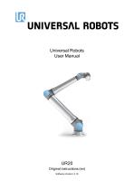
Universal Robots User Manual UR20 Original instructions (en) Software Version: 5.16
Open the catalog to page 1
User Manual Copyright © 2009–2024 by Universal Robots A/S. All rights reserved.
Open the catalog to page 2
The information contained herein is the property of Universal Robots A/S and shall not be reproduced in whole or in part without prior written approval of Universal Robots A/S. The information herein is subject to change without notice and should not be construed as a commitment by Universal Robots A/S. This document is periodically reviewed and revised. Universal Robots A/S assumes no responsibility for any errors or omissions in this document. Copyright © 2009–2024 by Universal Robots A/S. Copyright © 2009–2024 by Universal Robots A/S. All rights reserved. The Universal Robots logo is a registered...
Open the catalog to page 3
User Manual Copyright © 2009–2024 by Universal Robots A/S. All rights reserved.
Open the catalog to page 4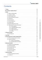
Part I Hardware Installation Manual 2.3. Safety Message Types 2.4. General Warnings and Cautions 2.9. Movement Without Drive Power 2.10. Safety-related Functions and Interfaces 2.10.2. Configurable Safety Functions 3. Lifting and Handling 3.1. Round Sling Use 5. Teach Pendant with 3-Position Enabling Device 5.1. 3PE Teach Pendant Button Functions 5.2.1. Freedrive with 3PE Buttons 5.2.2. Using Move Robot into Position 6.1. Workspace and Operating Space 7.1. Electrical Warnings and Cautions User Manual Copyright © 2009–2024 by Universal Robots A/S. All rights reserved.
Open the catalog to page 5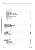
Copyright © 2009–2024 by Universal Robots A/S. All rights reserved. 7.4. Three Position Enabling Device 7.5. General Purpose Digital I/O 7.6. General Purpose Analog I/O 7.7. Remote ON/OFF control 7.11. Robot Connections: Robot Cable 7.12. Robot Connections: Base Flange Cable 7.14. Tool I/O Installation Specifications 7.15. Tool Power Supply 7.16. Tool Digital Outputs 7.17. Tool Digital Inputs 7.18. Tool Analogue Inputs 10. Robot Arm Cleaning and Inspection 13. Stopping Time and Stopping Distance 19. Safety Functions Tables Part II Software Manual User Manual
Open the catalog to page 6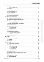
20.4.1. Freedrive Panel 20.5. Backdrive 20.5.1. Backdrive Inspection 20.6. Quick System Start-up 20.8. Robot Cyber Security 20.9. Operational Mode Selection 21. Software Safety Configuration 21.1. Setting a Software Safety Password 21.2. Changing the Software Safety Configuration 21.3. Applying a New Software Safety Configuration 21.4. Safety Configuration without Teach Pendant 21.5. Software Safety Modes 21.6. Software Safety Limits 21.8. Software Safety Restrictions 21.8.1. Tool Direction Restriction 21.8.2. Tool Position Restriction 21.9. Safe Home Position 22. Run Tab 22.1. Move Robot into...
Open the catalog to page 7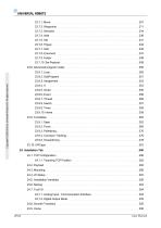
Copyright © 2009–2024 by Universal Robots A/S. All rights reserved. 23.8. Advanced program nodes 23.8.1. Loop 23.10. URCaps 24. Installation Tab 24.1. TCP Configuration 24.1.1. Teaching TCP Position 24.7.1. Analog Input - Communication Interface 24.7.2. Digital Output Mode
Open the catalog to page 8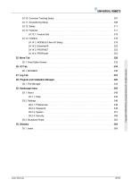
24.10. Conveyor Tracking Setup 24.13.1. Feature Edit 24.14. Fieldbus 24.14.1. MODBUS Client I/O Setup 25. Move Tab 25.1. Pose Editor Screen 28. Program and Installation Manager 28.1. File Manager 29. Hamburger menu 29.1. About 29.1.1. Help 29.2. Settings User Manual Copyright © 2009–2024 by Universal Robots A/S. All rights reserved.
Open the catalog to page 9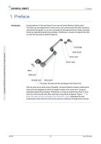
Copyright © 2009–2024 by Universal Robots A/S. All rights reserved. Congratulations on the purchase of your new Universal Robots e-Series robot. The robot can be programmed to move a tool, and communicate with other machines using electrical signals. It is an arm composed of extruded aluminium tubes and joints. Using our patented programming interface, PolyScope, it is easy to program the robot to move the tool along a desired trajectory. 2.1: The joints, the base and the tool flange of the Robot Arm. With six joints and a wide scope of flexibility, Universal Robots e-Series collaborative robot...
Open the catalog to page 10
1. Preface What Do the Boxes Contain • Control Box with 3PE Teach Pendant • Mounting bracket for the Control Box • Mounting bracket for the 3PE Teach Pendant • Key for opening the Control Box • Cable for connecting the robot arm and the Control Box (see detail 18 Technical Specifications on page 110) • Mains cable or power cable compatible with your region • Round sling or lifting sling • Tool flange adapter • Tool cable adapter Important Safety Notice The robot is partly completed machinery (see 12 Certifications on page 92) and as such a risk assessment is required for each installation of...
Open the catalog to page 11
Copyright © 2009–2024 by Universal Robots A/S. All rights reserved. The UR+ site (www.universal-robots.com/plus) is an online showroom that provides cutting-edge products to customize your UR robot application. You can find everything you need in one place—from end-effectors and accessories to vision cameras and software. All products are tested and approved to integrate with UR robots, ensuring simple set-up, reliable operation, smooth user experience, and easy programming. You can also access the UR+ Partner Program via our new software platform (plus.universal-robots.com), allowing you to...
Open the catalog to page 12
Part I Hardware Installation Manual User Manual Copyright © 2009–2024 by Universal Robots A/S. All rights reserved. Hardware Installation Manual
Open the catalog to page 13
Copyright © 2009–2024 by Universal Robots A/S. All rights reserved. Part I Hardware Installation Manual User Manual
Open the catalog to page 14
2. Safety This chapter contains important safety information, which must be read and understood by the integrator of Universal Robots e-Series robots before the robot is powered on for the first time. In this chapter, the first subsections are general. The later subsections contain specific engineering data relevant to enable setting up and programming the robot. Chapter describes and defines safety-related functions particularly relevant for collaborative applications. Instructions and guidance provided in chapter as well as in section are particularly important. It is essential to observe and...
Open the catalog to page 15


- Universal Robots industrial robot
- Automation software solution
- Universal Robots articulated robot
- 6-axis robot
- Handling robot
- Floor-mounted robot
- Interface software
- Compact robot
- Assembly robot
- Packaging robot
- Loading robot
- Applications robot
- Welding robot
- High-precision robot
- IP54 robot
- IP65 robot
- Robot for the electronics industry
- Palletizing robot
- 3-axis robot
- Universal Robots cobot