
- Catalogs
- Universal Marking Systems
- Stress Analysis Marker

Stress Analysis Marker

Stress Analysis Marker
Overview of Electrochemical Strain Grid Marking
Strain grid marking is a widely accepted technique for analyzing stress and deformation in sheet metal forming. The process involves applying geometric patterns directly onto metal surfaces using electrochemical oxidation, creating permanent, stress-free marks that do not compromise material integrity. These marks facilitate precise measurement of strain after forming.
Strain Grid Marking Equipment
ME96 Strain Grid Marking Kit
- Heavy-duty unit delivering up to 100 amps output.
- Suitable for large strain grid stencils.
- Includes pistol roller with trigger control, various output cables, felt pads, hand marker, electrolytes for ferrous and non-ferrous metals, and neutraliser.
- Designed for large-area marking applications.
ME3000TSG Strain Grid Marking Kit
- 20 amp output unit for smaller strain grid applications (typically 100mm wide marks).
- Features continuous or timed marking output.
- Supplied in a wooden case with four strain grid stencils, stencil paper, hand marker, footswitch for timer control, electrolytes, and neutraliser.
- Ideal for smaller, precise marking tasks.
Application and Analysis of Strain Grid Marking
Strain grid marking is extensively used in press-shops to optimize die try-out and troubleshoot stamping processes logically rather than by guesswork.
Why Circle Grid Analysis?
- Circles provide a non-directional pattern that allows measurement of complex plastic deformation in sheet metal.
- Square patterns are ineffective for strain measurement.
- A typical analysis area is approximately 250mm x 250mm to capture critical deformation zones.
Strain Measurement Principles
- Major strain (elongation) and minor strain are measured from the deformation of circles.
- Circle size and spacing are critical; small diameter circles (~2mm) closely spaced yield more accurate strain data.
- Strain is calculated as the change in circle diameter before and after forming.
Forming Limit Diagram (FLD)
- FLD plots major strain (e1) versus minor strain (e2) to distinguish successful from failed strain states.
- Constructed experimentally for different metals, FLDs vary by material type and grade.
- FLD is a key tool for assessing severity of strain and guiding process adjustments to avoid failure.
Importance of Minor Strain
- Minor strain can be positive, zero, or negative, significantly affecting forming success.
- Major strain alone is insufficient to predict failure; combined strain states must be considered.
Marking Procedure and Best Practices
- Prepare a large, flat workspace and degrease the test piece.
- Position equipment and stencil accurately on the test piece.
- Apply electrolyte-soaked felt pad over stencil.
- Use roller marker to evenly distribute electrolyte and activate marking unit.
- Roll over stencil pattern multiple times until clear marking is achieved.
- Remove stencil and felt pad; clean and store for reuse.
- Dry test piece and neutralize electrolyte residues if required.
- Press or form the test piece and measure strain results.
Neutralising solutions vary by metal type: MN1 for ferrous, MN2 for non-ferrous, and MN4 for immersion neutralising.
Measurement of Results
Strain is typically measured using graduated Mylar rules indicating percentage stretch of circles. Optical measuring systems are also available for enhanced precision.
Strain Grid Stencil Sizes and Patterns
Stencils come in three standard sizes (A, B, C) with pattern sizes ranging from 100mm x 280mm up to 400mm x 280mm. Various circle diameters and grid patterns are available, including specialized sizes down to 0.25mm dots and up to 20mm circles. Maximum stencil width is 300mm. Custom stencil designs can be manufactured upon request.
ME3000TSG Kit Stencils
- Four standard stencils (SG77A to SG77D) with circle sizes from 2.5mm to 6mm and pattern sizes around 130-198mm.
Critical Information and Recommendations
- Electrolyte selection is crucial: ME8 for ferrous metals (non-neutralising), ME3 for mild steel (requires neutralising), ME6 for stainless steel (requires neutralising), and ME5 for non-ferrous metals (requires neutralising).
- Marking is stress-free and permanent, preserving material integrity.
- Proper neutralisation after marking prevents corrosion or damage.
- FLD analysis is essential for understanding forming limits and preventing failures.
- Minor strain measurement is as important as major strain for accurate forming assessment.
- Use appropriate stencil size and pattern density to capture critical strain variations.
Contact and Support
Universal Marking Systems Ltd. provides full support and product information. Contact details include phone, fax, email, and website for sales and technical assistance.
Catalog excerpts

Electrochemical Strain Grid Marking Moving Marking Technology Forward
Open the catalog to page 1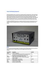
Strain Grid Marking Equipment Strain grid marking has become, over the years, the standard method for analysing stress in sheet metal forming. We manufacture two power units capable of producing the large, geometric patterns required for analysis. These patterns are laid down directly on to the surface of the sheet, prior to forming, by oxidising the material with electro-chemistry. This process is favoured, due to the ease of marking and speed of operation. More importantly however, the process is stress free, and ` forms a permanent mark without compromising the structure of the material. Most...
Open the catalog to page 2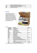
Mains cable and plug appropriate for country of use 1L of ME8 non-neutralising electrolyte for ferrous metal marking lL of ME5 electrolyte for non-ferrous metal marking lL neutraliser for ME5 electrolyte ME3000TSG. This machine gives a 20amp output and is suited for relatively small strain grid applications, typically 100mm wide marks. The marking output can be set for continuous output, or timed. The machine is supplied in a high quality wooden instrument case with all accessories required for marking including four strain grid stencils. The kit also contains stencil paper and an HM5 hand marker...
Open the catalog to page 3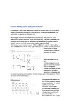
Universal Marking Systems Application Information This technique is used in many press-shops to reduce the time and costs of die try-out and to transform press trouble-shooting from a series or random guesses into logical process. The rudiments of this approach are described here. Why circle grid analysis? In sheet metal forming we are looking at the permanent plastic deformation of sheets by stretching, usually, in a complex way. If the sheet is marked in a nondirectional pattern (circles) then any deformation can be measured. If the pattern were, for example, squares, then fruitful measurements...
Open the catalog to page 4
that of 0.1” or 2.0mm diameter circles, close but not touching, in arrays of four, delimited in a square matrix for easy identification. Other patterns approximating this concept are also acceptable. Summarising at this stage: to be able to identify regions of high strain is useful in itself, but stain measurements from deformed small-diameter circles can provide far more useful information. Firstly, we must consider both major and minor strains. For a given major strain, e1, the minor strain e2, can be positive, zero or negative. This is illustrated in figure 3. The point of supreme importance...
Open the catalog to page 5
Major Strain It is often instructive to represent the strains in a panel by a plot of major values taken in the critical area shown in figure 6, with the values approaching a ‘ ceiling’ - this will be the minor strain limit from the FLD. Assume for a moment that this is a die- try out situation. It is now possible to see how close a successful pressing is to failure. If too close then action should be taken before putting tools into production. Only critical circles shown Figure 6. Severity point - how near is the part to failure? Take now a production splitting problem represented in figure...
Open the catalog to page 6
Marking Information The Universal Marking Systems strain grid marking equipment can be used on ferrous and nonferrous metals, producing either an oxide or etched mark on the test piece. The marking process is quite simple and fast and is ideal for on-site testing. It is important to follow the instructions of the equipment and solutions being used. Please contact us or your local Agent or distributor for copies of our product sheets. Ferrous metals. There are a number of electrolytes that can be used, but ME8 is good choice due to its nonneutralising properties. It will produce a good dark oxide...
Open the catalog to page 7
neutralising solution (MN1 for ferrous metals or MN4 as an immersion neutraliser or MN2 for non-ferrous metals). Press or form the test piece and measure the results. Measuring the results. The simplest way is to use our Universal Marking Systems Mylar rules. These are graduated in the percentage of stretch of the circle. Optical measuring systems are also available.
Open the catalog to page 8
Universal Marking Systems Strain Grid stencil sizes Universal Marking Systems Strain grid stencils are produced in three standard sizes. Pattern style.
Open the catalog to page 9
3/4 inch squares with 1 inch circles
Open the catalog to page 11
0.1 inch circles in 0.25 inch squares O.linch circles
Open the catalog to page 12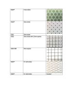
5mm circles 5mm circles with 2.5mm squares
Open the catalog to page 13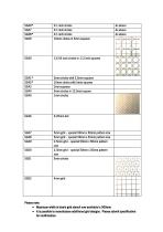
0.1 inch circles 0.1 inch circles 0.1 inch circles 10mm circles in 5mm squares 13/64 inch circles in 1/2 inch squares 5mm circles with 2.5mm squares 10mm circles with 5mm squares 2mm squares 5mm circles in 12.5mm square 1mm circles 5mm grid – special 50mm x 50mm pattern size 5mm grid – special 50mm x 35mm pattern size 2.5mm grid – special 50mm x 50mm pattern size 2.5mm grid – special 50mm x 35mm pattern size 5mm circles As above As above As above Please note: Maximum width of strain grid stencil now available is 300mm It is possible to manufacture additional grid designs. Please submit specification...
Open the catalog to page 14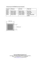
Strain grid stencils for ME3000TSG strain grid marking kits Strain grid ref. No. SG77A SG77B SG77C SG77D Marking size Stencil size Pattern style 6mm circles 2.5mm circles 5mm circles 2.5mm circles in 6mm squares Stencil size Marking size Universal Marking Systems Ltd. Head Office: Mount Road, Feltham, Middx. TW13 6AR. ENGLAND Sales - Tel. 020 8898-4884/5 Fax. 020 8898-9891. e-mail: [email protected] www.ums.co.uk
Open the catalog to page 15All Universal Marking Systems catalogs and technical brochures

Archived catalogs
 DataMatrix Leaflet
4 Pages
- Marking machine
- Laser marking machine
- Metal marking machine
- Benchtop marking machine
- Automatic marking workstation
- Industrial marking machine
- Compact marking machine
- Fiber laser marking machine
- Metal marking machine
- Programmable marking machine
- Industrial marking system
- Marking tool
- Digital marking machine
- Metal marking system
- PCB etching machine
- Semi-automatic marking machine
- Engraving pen
- Hand marking tool
- Numerical control marking machine