MX
1 /6Pages

MX
1 /6Pages
Catalog excerpts

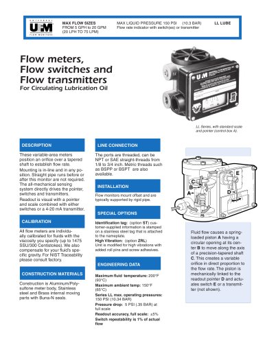
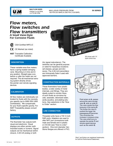
MAX FLOW SIZES FROM 15 TO 160 GPM (60 TO 600 LPM) MAX LIQUID PRESSURE FROM 100 TO 200 PSI (6.90 TO 13.79 BAR) Flow meters, Flow switches and Flow transmitters F L O W A Medium Vane-Style For Corrosive Fluids CSA Certified NRTL/C CE Marked (as noted) NIST Traceable Calibration Certificate Available DESCRIPTION These variable-area flow meters have a spring-loaded swinging vane. Mounting is in-line and in any position. Straight pipe runs, before or after the meter, are not required. The all-mechanical sensing system directly drives the pointer and remote signaling devices. CALIBRATION All flow meters are individually calibrated for fluids with the viscosity you specify (up to 3000 SSU (650 Centistokes). We compensate for your fluid's specific gravity. For NIST Traceability please consult factory. OUTPUTS The flowmeter has outputs both visual and electronic. Visual displays are either pointer (with inscribed scale) or numeric. Signal outputs can be mechanical switch closure, 4-20 mA analog or both (for signal redundancy). The switches can MX shown with "A" style control box. be general purpose or rated for hazardous locations (all classes, groups and divisions). The 4-20 mA transmitters are Intrinsically Safe if used with approved barriers. CONSTRUCTION MATERIALS These flowmeters have plastic bodies, a wide variety of metal internals, and fittings. They are ideally suited to monitor flows of such fluids as corrosive liquids,seawater, deionized water, acids,caustics, and plating solutions. See selections in the “How to Order”section. LINE CONNECTION Threaded units have 2 ½ inch -12 SAE ports. Adapters are used to offer NPT female port connections in a variety of materials and sizes (see “How to Order” section). Van Stone flanges are offered in a variety of sizes in PVC. Fluid enters at A, passes around the semi-circular vane B, exits at outlet C. The vane resists the flow because of the spring D. The further the vane is pushed the larger the passageway E becomes. This minimizes the increase in pressure drop. The vane shaft turns to operate the pointer F and remote signal devices such as the switch G. Viton® and Kalrez™ are registered trademarks for DuPont Performance Elastomers.
Open the catalog to page 1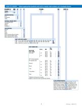
EXAMPLE: MX - V SERIES Medium Select appropriate symbols and build a model code number, as in example shown: HOUSING MATERIAL PVC Polysulfone Tefzel INTERNAL MOVING PARTS 316 Stainless Steel = I Titanium = T Monel = L Hastelloy C = C SEAL MATERIAL Buna N = B EPR = E Viton = F Kalrez = J Kalrez (dymanic)/Buna N (static) = A Kalrez (dymanic)/EPR (static) = H Kalrez (dynamic)/Viton (static) = K MAX FLOW RATE LIQUIDS GPM 1Ø, 15, 2Ø, 3Ø, 4Ø, 5Ø, 6Ø, 7Ø, 8Ø, 9Ø, 1ØØ, 11Ø, 12Ø, 13Ø, 14Ø, 15Ø, 16Ø = GM LPM 4Ø, 5Ø, 6Ø, 7Ø, 8Ø, 9Ø, 1ØØ, 15Ø, 2ØØ, 25Ø, 3ØØ, 35Ø, 4ØØ, 5ØØ, 6ØØ = LM CMH 2.25, 2.5, 3, 4, 5,...
Open the catalog to page 2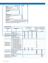
SERVICE Oil and dust tight (Type 12) = N Weatherproof (Type 4) = W Weatherproof, corrosion proof (Type 4X) = X FLOW DIRECTION Left to right = R Right to left = L Up = U Down = D SPECIAL OPTIONS Stainless steel ID tag for customer supplied information Tempered glass window Manual override Dual spring Clearance vane for ≥ 16 GPM SWITCH SETTING No symbol = Lowest possible setting (usually 10% of maximum flow) Desired set point is assumed to be in flow units already selected (GPM). Give flow rate 5D followed by a “D” for flow going down (flow failure) or a “U” for flow going up. Example, 5D indicates...
Open the catalog to page 3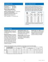
ENGINEERING DATA FLOW & PRESSURE DROP Maximum operating temperature: PVC housing: 100°F (38°C) Polysulfone housing: 200°F (95°C) Tefzel housing: 200°F (95°C) Maximum ambient temperature: 130°F (UL listed to 105°F (40°C; for hazardous locations -13 to +104°F) Units with max flows to 80 GPM (300 LPM) impose a pressure drop that increases with flow, from 1.9 to 3.8 PSI. Higher flow-rated models are made possible by having a partial bypass (which raises minimum indicated flow), or dual springs (which raises the pressure drop). The table shows minimum flow rates and pressure drops (PSI) (at max flow...
Open the catalog to page 4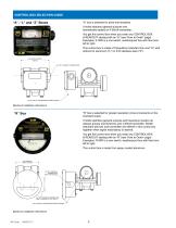
CONTROL BOX SELECTION GUIDE “A” box is selected for price and simplicity. It holds switches (general purpose and hermetically sealed) or 4-20mA transmitter. You get this control box when you order any CONTROL BOX & READOUT starting with an “A” (see "How to Order" page). Examples: A1WR is a one switch, weatherproof box with flow from left to right. This control box is made of Polysulfone (standard low cost “A”) with options for aluminum (“L”) or 316 stainless steel (“Z”). 6.25 PORT-TO-PORT [159mm] 3/4" NPT CONDUIT CONNECTION R6.13 [156mm] APPROXIMATE SWING RADIUS Maximum installation dimensions...
Open the catalog to page 5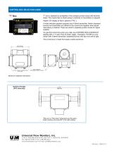
CONTROL BOX SELECTION GUIDE “T” box is selected for availability of two isolated junction boxes with terminal strips. This means that no direct wiring to switches or transmitters is required. Digital LCD display of flow is optional (“TXL”). It holds switches (general purpose) and 4-20mA transmitter. Switch (standard service) and transmitter are offered in this control box together when signal redundancy is desired. These are wired to separate junction boxes for signal isolation. You get this control box when you order any CONTROL BOX & READOUT starting with a “T” (see "How to Order" page). Examples:...
Open the catalog to page 6All UNIVERSAL FLOW MONITORS catalogs and technical brochures
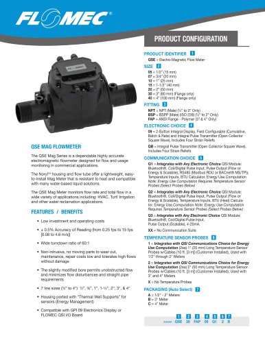 FLOMEC® QSE
2 Pages
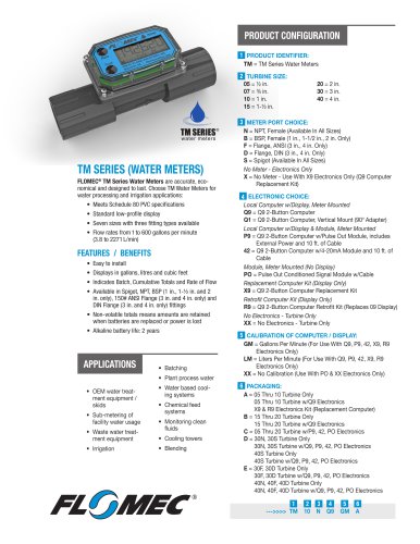 TM SERIES
2 Pages
 G2 SERIES
2 Pages
 Piston Inline PI
6 Pages
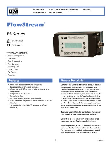 FS series
4 Pages
 FP series
4 Pages
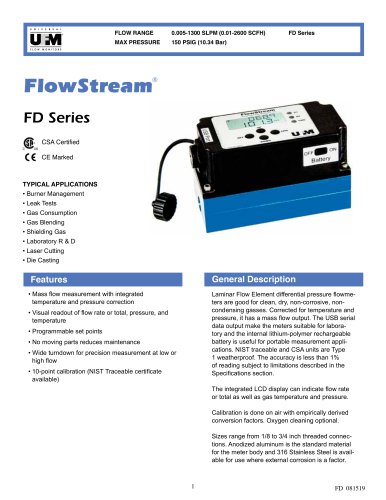 FD series
4 Pages
 Coolpoint Large Series
4 Pages
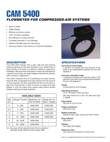 cam 5400
2 Pages
 XHF
XHF5 Pages
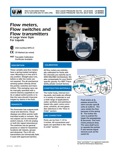 LN series
5 Pages
 CAM 5200
2 Pages
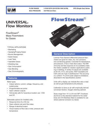 OFS simplified single gas
3 Pages
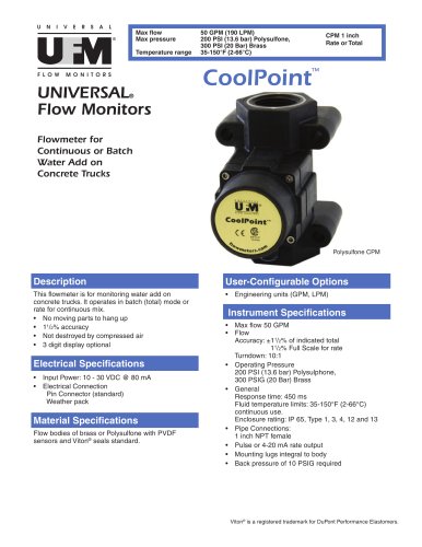 CPM
CPM4 Pages
 Insite Lit no TX
6 Pages
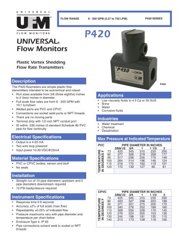 P420 Plastic Vortex Meter
2 Pages
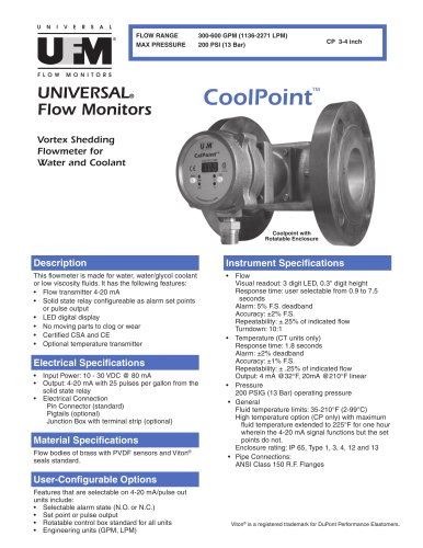
 CP V8
CP V82 Pages
 LL AX0 lube
3 Pages
 Flow Sensor
2 Pages
 Vortex Shedding Flowmeter
4 Pages


Archived catalogs

- Volume flow monitor
- Liquid flow monitor
- Waterproof flow meter
- Gas flow monitor
- Stainless steel flow monitor
- Precision flow meter
- In-line flow meter
- Water flow monitor
- Compact flow monitor
- RS485 flow monitor
- Mass flow monitor
- Digital flow monitor
- Flow meter with display
- IP65 flow monitor
- DN50 - 2" flow meter
- DN25 - 1" flow monitor
- Flange flow meter
- Flow controller
- High-accuracy flow meter