CPM
1 /4Pages
CPM
1 /4Pages
Catalog excerpts

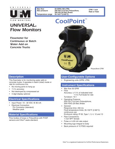
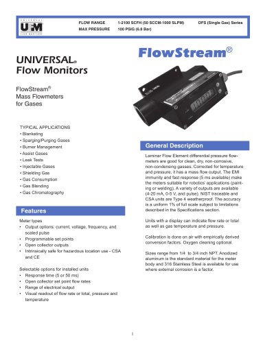
U N I V E R S A L Max ow Max pressure ® Temperature range F L O W 50 GPM (190 LPM) 200 PSI (13.6 bar) Polysulfone, 300 PSI (20 Bar) Brass 35-150°F (2-66°C) CPM 1 inch Rate or Total ™ M O N I T O R S UNIVERSAL Flow Monitors CoolPoint ® Flowmeter for Continuous or Batch Water Add on Concrete Trucks Polysulfone CPM Description User-Congurable Options This owmeter is for monitoring water add on concrete trucks. It operates in batch (total) mode or rate for continuous mix. • No moving parts to hang up • 11/2% accuracy • Not destroyed by compressed air • 3 digit display optional • Electrical Specications • • • • Input Power: 10 - 30 VDC @ 80 mA Electrical Connection Pin Connector (standard) Weather pack Instrument Specications • • Material Specications Flow bodies of brass or Polysulfone with PVDF sensors and Viton® seals standard. Engineering units (GPM, LPM) • • • • Max ow 50 GPM Flow Accuracy: ±11/2% of indicated total 11/2% Full Scale for rate Turndown: 10:1 Operating Pressure 200 PSI (13.6 bar) Polysulphone, 300 PSIG (20 Bar) Brass General Response time: 450 ms Fluid temperature limits: 35-150°F (2-66°C) continuous use. Enclosure rating: IP 65, Type 1, 3, 4, 12 and 13 Pipe Connections: 1 inch NPT female Pulse or 4-20 mA rate output Mounting lugs integral to body Back pressure of 10 PSIG required Viton® is a registered trademark for DuPont Performance Elastomers.
Open the catalog to page 1
How To Order Select the appropriate symbols to build a model code: MODEL CODES SERIES SYMBOL=FEATURE BODY MATERIAL OUTPUT AND DISPLAY ORIENTATION -M1* = Brass C1* = 5 pin connector only D3* = Pulse out with 3 digit display of total N2* = Flow up -M5 = Polysulfone C7 = 3 feet of 3-wire cable added to the pin connector terminating in a PG7 "weather pack" connector D1 = 4-20 mA out with 3 digit of rate display N3 = Flow left D4E10 = pulse out no display D4E1 = 4-20 mA out with no display CPM8 CABLING N1 = Flow right N4 = Flow down * Indicates this is a standard option for the product. If you leave...
Open the catalog to page 2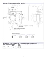
INSTALLATION DRAWING – BASIC METERS CABLE POSITION N4 5.00 Max. [127mm] 3.25 Max. [83mm] C 1.31 [33mm] B OUT 4.59 Max. [117mm] CABLE POSITION N1 CABLE POSITION N3 A MOUNTING LUGS FOR Ø.31 (5/16) BOLTS. (4) PLACES. CABLE (CONNECTOR) SHOWN AT POSITION N2. Dimensions in Inches (mm) Body Material A B C M1 3.13 (79) 2.31 (59) 1.56 (40) M5 2.88 (73) 2.50 (64) 2.00 (51) ACCESSORY CABLES AVAILABLE FOR PIN CONNECTOR METERS Series Description CP 5 pin female Length in Meters 1 3 10 Part Number 6241-1M 6241-3M 6241-10M 3
Open the catalog to page 3
PIN CONNECTOR PINOUTS Note that on this option, the ow relay contacts are open collector switches. To get a pulse out, install an external 2-10 K Ohm resistor where indicated. TOTALIZER WITH PULSE OUTPUT WHITE NOT USED BROWN 2 1 +24 Vdc POWER SUPPLY GRAY 5 FLOW SIGNAL PULSE OUTPUT 4 3 BLACK SUPPLY GROUND (REDUNDANT) BLUE SUPPLY GROUND PIN CONFIGURATION: • 1: + 24 VDC power supply • 2: not used • 3: supply ground • 4: supply ground • 5: ow signal pulse output Note: There is an internal 10K Ω pull-up resistor on the pulse output line (pin 5). FLOW RATE WITH 4-20MA OUTPUT WHITE 4-20 mA FLOW SIGNAL...
Open the catalog to page 4All UNIVERSAL FLOW MONITORS catalogs and technical brochures
 FLOMEC® QSE
2 Pages
 TM SERIES
2 Pages
 G2 SERIES
2 Pages
 Piston Inline PI
6 Pages
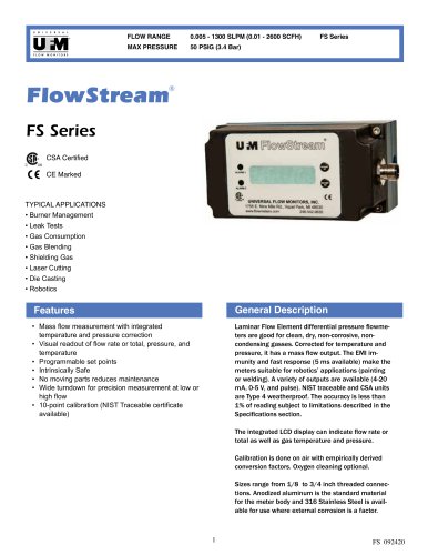 FS series
4 Pages
 FP series
4 Pages
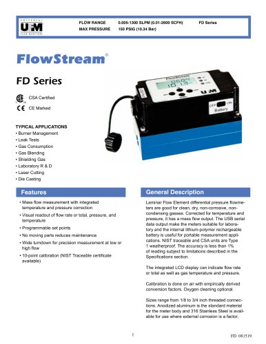 FD series
4 Pages
 Coolpoint Large Series
4 Pages
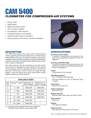 cam 5400
2 Pages
 MX
MX6 Pages
 XHF
XHF5 Pages
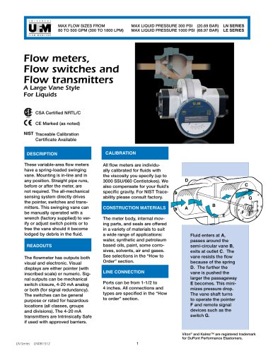 LN series
5 Pages
 CAM 5200
2 Pages
 OFS simplified single gas
3 Pages
 Insite Lit no TX
6 Pages
 P420 Plastic Vortex Meter
2 Pages
 CP V8
CP V82 Pages
 LL AX0 lube
3 Pages
 Flow Sensor
2 Pages
 Vortex Shedding Flowmeter
4 Pages


Archived catalogs

- Flowmeter
- Volume flow monitor
- Liquid flow monitor
- Waterproof flow meter
- Gas flow monitor
- Stainless steel flow monitor
- Precision flow meter
- In-line flow meter
- Water flow monitor
- Compact flow monitor
- RS485 flow monitor
- Mass flow monitor
- Digital flow monitor
- Flow meter with display
- IP65 flow monitor
- DN50 - 2" flow meter
- DN25 - 1" flow monitor
- Flange flow meter
- Flow controller
- High-accuracy flow meter