
- Catalogs
- UNIVERSAL FLOW MONITORS
- AX0 4-20 mA transmitter SN AX0 lube

AX0 4-20 mA transmitter SN AX0 lube

AX0 4-20 mA transmitter SN AX0 lube
- Flow range: 0.5 to 20 GPM (2 to 75 LPM)
- Maximum liquid pressure: 300 PSI (20.69 BAR)
- Construction materials: Aluminum body with nylon, stainless steel internal parts, Buna-N seals
- Threaded line connections: NPT (1/4 to 3/4"), SAE (1/4 to 5/8"), BSPP, BSPT
- Maximum fluid temperature: 200°F (95°C)
- Maximum ambient temperature: 150°F (65°C)
- Readout accuracy: ±5% full scale
- Switch repeatability: 1% of actual flow
Catalog excerpts

MAX FLOW SIZES FROM 0.5 TO 20 GPM (2 TO 75 LPM) MAX LIQUID PRESSURE 300 PSI (20.69 BAR) Flow rate indicator with switch(es) or transmitter. SN LUBE Flow meters, Flow switches and Flow transmitters For Circulating Lubrication Oil SN Series shown with “A” style control box DESCRIPTION CONSTRUCTION MATERIALS These are variable area meters with a spring biased semi-circular vane that opens wider with more ow. They are installed in-line in any position. Straight pipe runs before or after the meter are not required. The simple mechanical connection directly drives pointers, switches and transmitters. The body is aluminum with nylon. Internal moving parts are stainless steel. Seals are Buna-N. CALIBRATION All ow meters are individually calibrated for uids with the viscosity you specify (up to 3000 SSU/660 Centistokes). We also compensate for your uid’s specic gravity. For NIST Traceability please consult factory. FLOW & PRESSURE DROP Max Flow in GPM (LPM) 8 (32) 9-12 (45) 15 (56) 16 (60) 20 (75) Pressure drop in PSI Min Max 1.9 2.5 1.9 4 1.9 5 1.9 5.5 1.9 6 F C LINE CONNECTION Ports are threaded. Threaded ports can be NPT (1/4 to 3/4") or SAE straight thread (1/4 to 5/8"). Metric threads such as BSPP or BSPT are also available. D A B G E ENGINEERING DATA Maximum uid temperature: 200°F (95°C) Maximum ambient temp: 150°F (65°C) Series SN max. operating pressure: 300 PSI (20.69 BAR) Readout accuracy, full scale: ±5% Switch repeatability is 1% of actual ow INSTALLATION Flow monitors mount in-line and are typically supported by rigid pipe. 1 Fluid enters at A, passes around the semi-circular vane B. exits at outlet C. The vane resists the ow because of the spring D. The further the vane is pushed the larger the passageway E becomes. This minimizes the pressure drop. The vane shaft turns to operate the pointer F and remote signal devices such as the switch G.
Open the catalog to page 1
A1 W SERVICE Oil and dust tight (Type 12) = Weatherproof (Type 4) = Weatherproof, corrosion proof (Type 4X) = = = = = ST - 2D N W X FLOW DIRECTION Left to right Right to left Up Down L- R L U D SPECIAL OPTIONS High vibration modication (Order with A1B switch below) Stainless steel ID tag = = ZRL ST SWITCH SETTING Desired set point is assumed to be in ow units already selected (GPM). Give ow rate followed by a “D” for ow going down (ow failure) or a “U” for ow going up. Example, 2D indicates a setting of 2 GPM in declining ow. Leaving this blank will result in the switch being set at the minimum...
Open the catalog to page 3All UNIVERSAL FLOW MONITORS catalogs and technical brochures
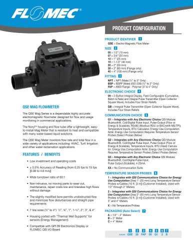 FLOMEC® QSE
2 Pages
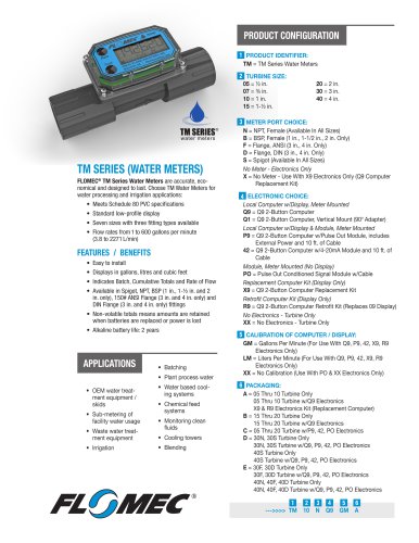 TM SERIES
2 Pages
 G2 SERIES
2 Pages
 Piston Inline PI
6 Pages
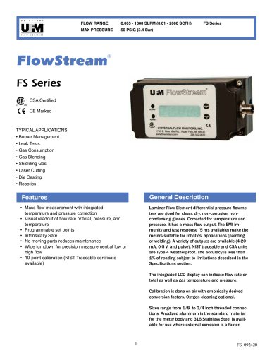 FS series
4 Pages
 FP series
4 Pages
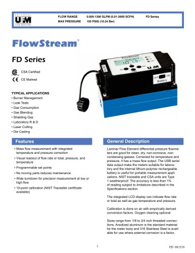 FD series
4 Pages
 Coolpoint Large Series
4 Pages
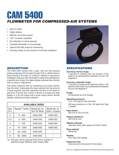 cam 5400
2 Pages
 MX
MX6 Pages
 XHF
XHF5 Pages
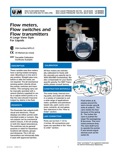 LN series
5 Pages
 CAM 5200
2 Pages
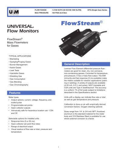 OFS simplified single gas
3 Pages
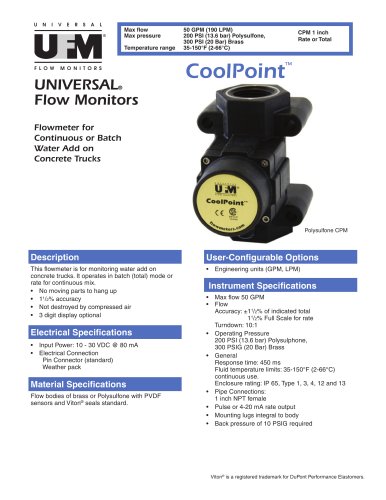 CPM
CPM4 Pages
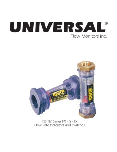 Insite Lit no TX
6 Pages
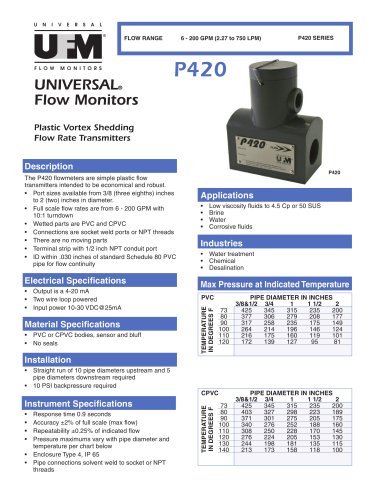 P420 Plastic Vortex Meter
2 Pages
 CP V8
CP V82 Pages
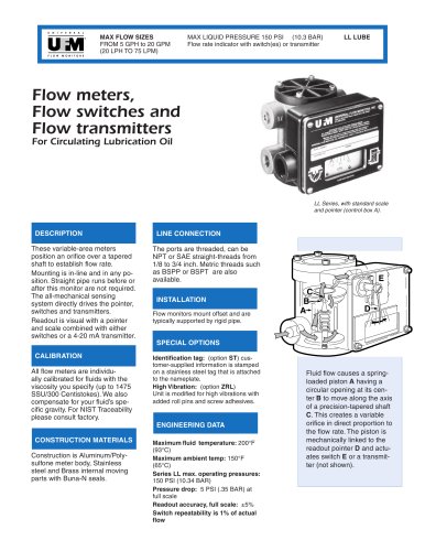 LL AX0 lube
3 Pages
 Flow Sensor
2 Pages
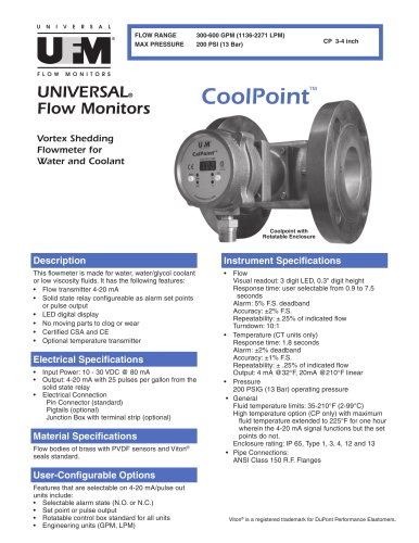 Vortex Shedding Flowmeter
4 Pages







Archived catalogs

- Volume flow monitor
- Liquid flow monitor
- Waterproof flow meter
- Gas flow monitor
- Stainless steel flow monitor
- Precision flow meter
- In-line flow meter
- Water flow monitor
- Compact flow monitor
- RS485 flow monitor
- Mass flow monitor
- Flow meter with display
- Digital flow monitor
- IP65 flow monitor
- DN25 - 1" flow monitor
- DN50 - 2" flow meter
- Flange flow meter
- Flow controller
- High-accuracy flow meter