- Catalogs
- UNIVER Group
- RETRACTABLE LOCATING PIN UNITS


RETRACTABLE LOCATING PIN UNITS

RETRACTABLE LOCATING PIN UNITS
The document provides technical specifications and instructions for the installation, connection, and maintenance of pneumatic retractable locating pin units by UNIVER S.p.A. It emphasizes safety measures and proper handling by authorized personnel to ensure staff security.
Safety and Handling
All operations must be conducted by authorized personnel, with safety measures in place to prevent risks, particularly during maintenance. Appropriate signaling or security systems should be installed near hazardous areas.
Fixing Instructions
The unit can be fixed using the front or side part of the clamp housing. Ensure the unit is undamaged before installation. Use two Ø8H7 pins for positioning and M8 screws for securing, with a tightening torque of 15 Nm.
Connection Instructions
Connect the clamp's sensor to its electric supply and the pneumatic tube using specified fittings:
- Series LCI40: G1/8” fittings
- Series LCM50, LCP50, LCA63: G1/4” fittings
Electrical Sensor Specifications
- Supply voltage: 10 ÷ 30 Vdc
- Supply current without load: < 20 mA
- Rated operational current: Max 30 mA
- Output logic: PNP N.O.
- LED indicators: Green (supply), Red (close position), Yellow (open position)
Connector Orientation and Sensor Replacement
To orientate the connector, unscrew, open, rotate, and secure it. For sensor replacement, unscrew the sensor, insert a new one, and secure it without removing the air supply.
Maintenance Recommendations
The unit requires no specific programmed maintenance but recommends monthly external cleaning of welding deposits using non-aggressive, non-corrosive detergents.
Catalog excerpts

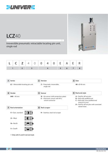
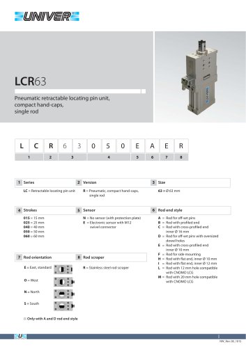
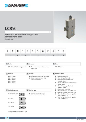
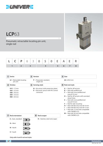
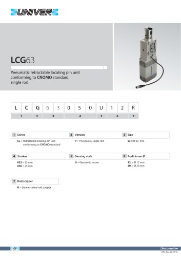
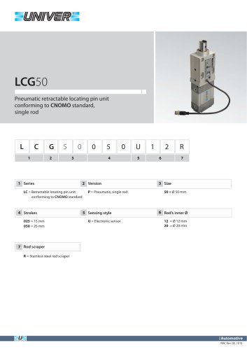
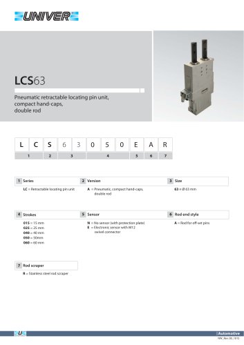
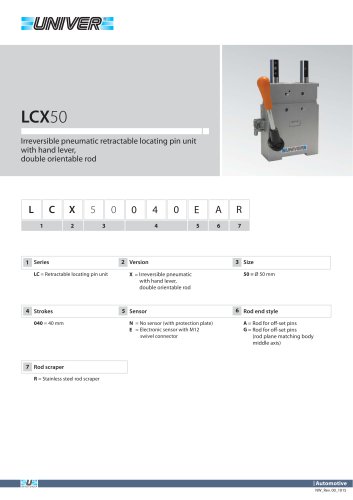
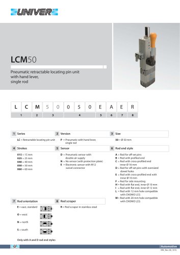
Pneumatic retractable locating pin units The handling, positioning as well as the maintenance operations have to be carried out by observing all conditions which guarantee the security of the staff and only by authorized personnel.The residual risks regarding the sole maintenance phase consist in the squashing of the upper parts of the operator's body. As a preventive measure an appropriate signalling or an adequate security system placed near the dangerous areas and which have to be installed by the user will alert the operator. The fixing of the unit to the equipment can be carried out by using the front, or side part of the housing of the clamp. Before installing the retractable locating pin unit, make sure that it hasn't been damaged during transport or handling operations. - Insert two hardened and grinded 08H7 pins into the special seats such as to locate the clamp - Fix it steadily by using the indicated M8 screws, and make sure that they are about 8 mm deep in the thread holes, limiting the tightening > Instructions for the connection of the clamp to its energy source Connect the sensor of the clamp to its electric supply unit. Then connect the pneumatic tube by means of suitable pneumatic fittings according to the specification below: Operating pressure from 4 to 8 bar ELECTRIC FEATURES Supply voltage Supply current without load Rated operational current Output logic Mole contacts Micro C Ml 2
Open the catalog to page 1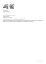
How to orientate the connector 1. Unscrew the screw of the connector 2. Open the cover 3. Rotate the connector 4. Close the cover and screw it How to replace the sensor 1. It is not necessary to remove the air supply 2. Unscrew the sensor’s screw 3. Insert a new sensor 4. Screw the sensor to its housing > Type and frequency of controls and/or maintenance work The unit has been designed and constructed in such a way that specific programmed maintenance is not necessary; anyway, a monthly external cleaning of the welding deposits with suitable, not aggressive and not corrosive detergents is recommended....
Open the catalog to page 2All UNIVER Group catalogs and technical brochures
 JLE
JLE5 Pages
 HZRS
HZRS2 Pages
 MP Clamping cylinders
3 Pages
 AC-N NAMUR valve
2 Pages
 HZ9N
HZ9N1 Page
 HE/HF tubes
1 Page
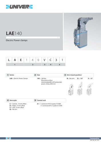 LAE140 Electric power clamps
4 Pages
 Modular Tooling System - GR8
52 Pages
 PRODUCT RANGE
44 Pages
 ATEX PRODUCT RANGE
14 Pages
 NEWS 2017-2018
32 Pages
 NEWS 2016
16 Pages
 PRODUCT OVERVIEW
228 Pages
 Product range
44 Pages
 ATEX Certified products
14 Pages
 NEWS 2017
32 Pages
 Valves
210 Pages
 ACCESSORIES
54 Pages
 UBH40_UNIVERSAL Power clamps
6 Pages
 PRODUCT RANGE
32 Pages
 LAGP605_Pneumatic power pivot
13 Pages
 LAGP600_Pneumatic power pivot
13 Pages
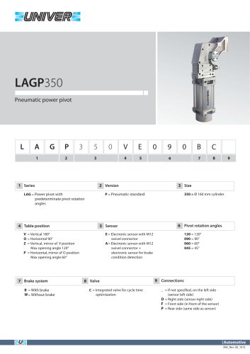 LAGP350_Pneumatic power pivot
13 Pages
 LAGP300_Pneumatic power pivot
13 Pages
 LAGP210_Pneumatic power pivot
13 Pages
 LAGP170_Pneumatic power pivot
13 Pages
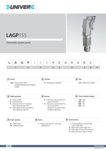 LAGP155_Pneumatic power pivot
13 Pages
 LAGP150_Pneumatic power pivot
13 Pages
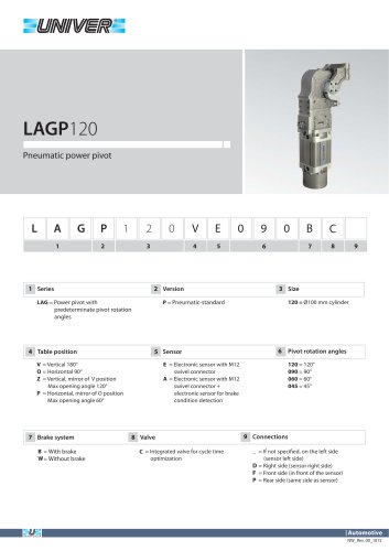 LAGP120_Pneumatic power pivot
13 Pages
 LAGP080_Pneumatic power pivot
13 Pages
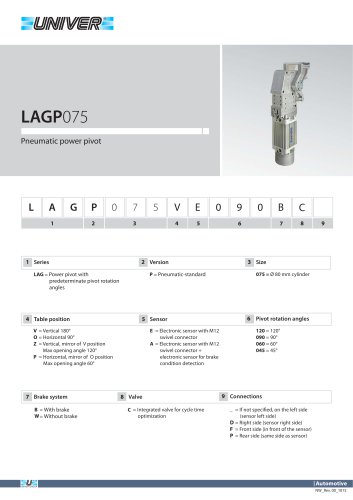 LAGP075_Pneumatic power pivot
13 Pages
 PRP1100_Marking units
3 Pages
 PRP0500_Marking Units
4 Pages
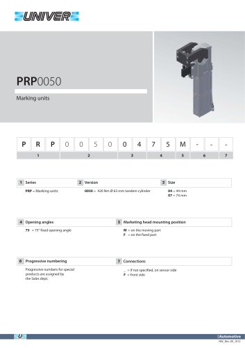 PRP0050_Marking units
3 Pages
 PRP0025_Marking units
2 Pages
 LGP40_ Pneumatic Grippers
7 Pages
 LGP32_ Pneumatic Grippers
7 Pages
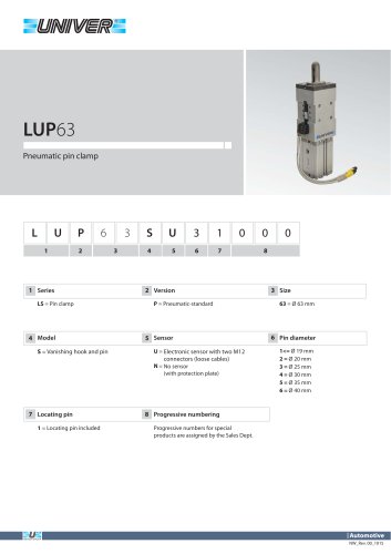 LUP63_Pneumatic pin clamp
2 Pages
 LSP60_Pneumatic pin clamp
3 Pages
 LSP50U_Pneumatic pin clamp
3 Pages
 LSP32_Pneumatic pin clamp
3 Pages
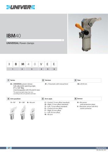 IBM40_UNIVERSAL Power clamps
6 Pages
 IBP40_UNIVERSAL Power clamps
6 Pages
 UBH63_UNIVERSAL Power clamps
6 Pages
 UBM40_UNIVERSAL Power clamps
6 Pages
 UBM50_UNIVERSAL Power clamps
10 Pages
 UBM63_UNIVERSAL Power clamps
10 Pages
 UBM80_UNIVERSAL Power clamps
10 Pages
 UBP32_UNIVERSAL Power clamps
4 Pages
 UBP50_UNIVERSAL Power clamps
6 Pages
 UBP63_UNIVERSAL Power clamps
6 Pages
 UBP80_UNIVERSAL Power clamps
8 Pages
 UBQ40_UNIVERSAL Power clamps
8 Pages
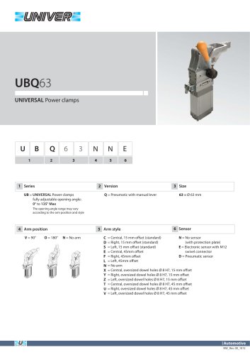 UBQ63_UNIVERSAL Power clamps
6 Pages
 UBT40_UNIVERSAL Power clamps
6 Pages
 Product Overview
228 Pages
 HIGH TECH
75 Pages
 CYLINDERS
67 Pages
 AUTOMOTIVE DIVISION
24 Pages
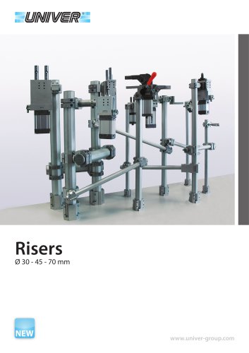 RISERS
4 Pages
 LGP32-40 Pneumatic Grippers
16 Pages
 GR8-Modular Tooling System
44 Pages
 M series
1 Page
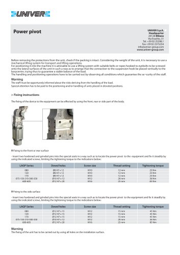 POWER PIVOTS
2 Pages
 PIN CLAMPS
2 Pages
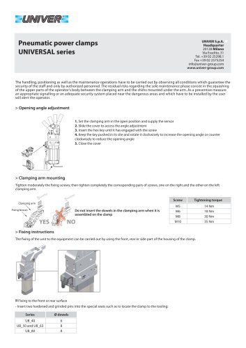 CLAMPS
2 Pages
 AIR TREATMENT
14 Pages
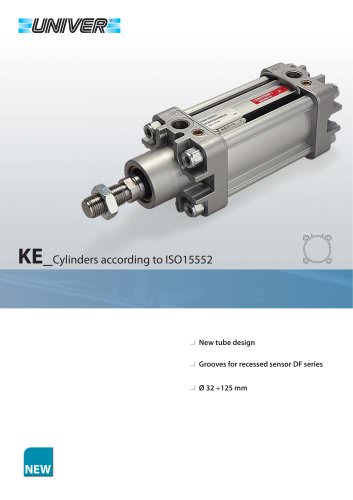 KE_Cylinders according to ISO 15552
10 Pages
 HZE_Additional components
4 Pages
 HZE_Air treatment units
14 Pages
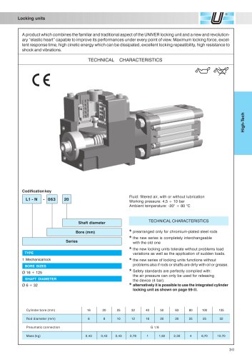 L1/L6_Locking unit for cylinders
6 Pages
 HZE_Air treatment units
12 Pages
 fittings
36 Pages
 PS_COMBOBOX valves
12 Pages
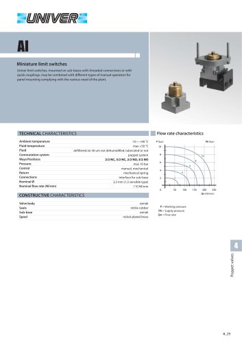 AI_Miniature limit switches
4 Pages
 CH_2/2 - 3/2 G1/8 poppet valves
4 Pages
 A_15 mm Microvalves
6 Pages
 B10_Nanovalvole 10 mm ISO 15218
2 Pages
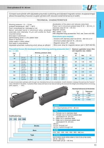 OV_Oval cylinders Ø 18-80 mm
5 Pages
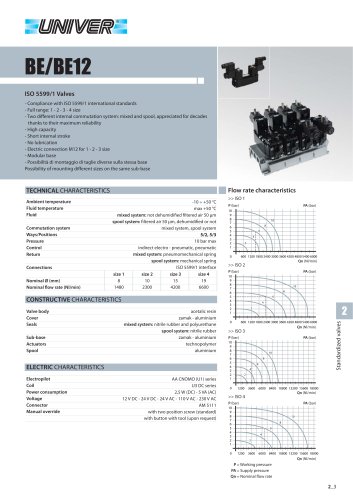 BE/BE12_ISO 5599/1 Valves
12 Pages
 Rodless cylinders Ø 16-50 mm
12 Pages
 Rotary actuators Ø 32-125 mm
3 Pages