- Catalogs
- UNIVER Group
- POWER PIVOTS
POWER PIVOTS
1 /2Pages
POWER PIVOTS
1 /2Pages
Catalog excerpts

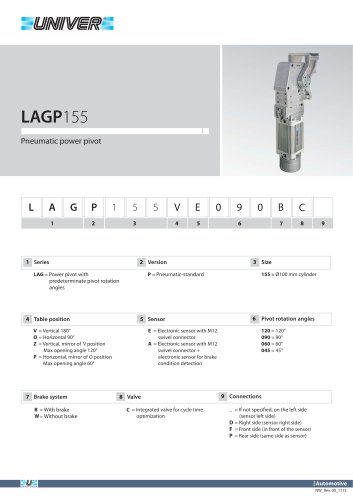
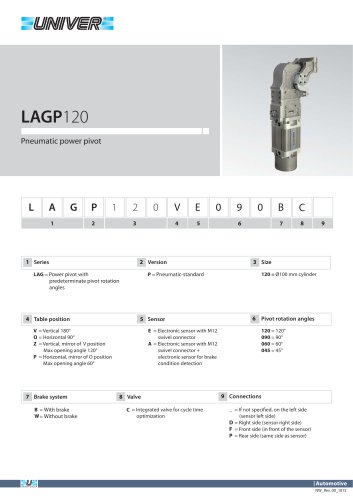
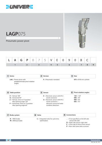
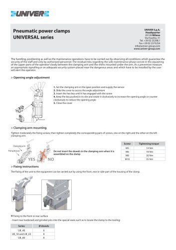
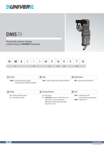
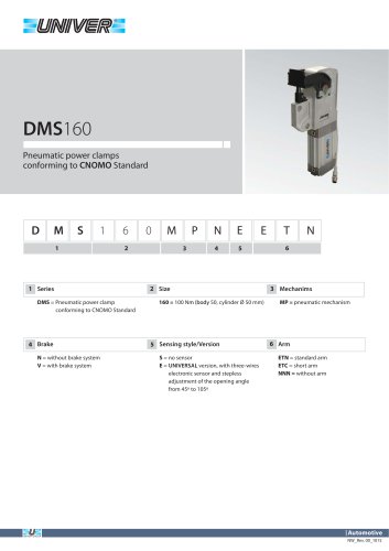
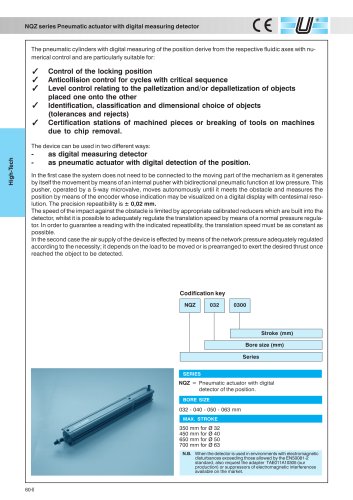
Power pivot Before removing the protections from the unit, check if the packing is intact. Considering the weight of the unit, it is necessary to use a mechanical lifting system for transport and lifting operations. For positioning it into the machine it is advisable to use a lifting system with suitable belts or ropes hooked to eyebolts to be screwed onto the lateral surfaces of the unit in such a way as to arrange that the connection to the suspension hook be placed vertically to the barycentre, trying thus to guarantee a stable balance of the load. The handling and positioning operations have to be carried out by observing all conditions which guarantee the se-icurity of the staff. The staff must be opportunely informed about the risks deriving from the handling of the load. Special attention has to be paid to the positioning and/or handling of units placed in elevated positions. The fixing of the device to the equipment can be effected by using the front, rear or side part of the body. Fixing to the front or rear surface - Insert two hardened and grinded pins into the special seats in a way such as to locate the power pivot to the equipment and fix it steadily by using the indicated screws, limiting the tightening torque to the indications below: ■ Fixing to the side surface - Insert two hardened and grinded pins into the special seats in a way such as to locate the power pivot to the equipment and fix it steadily by using the indicated screws, limiting the tightening torque to the indications below: The fixing of the unit has to be carried out by using all holes on the installation surface.
Open the catalog to page 1
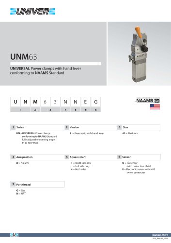
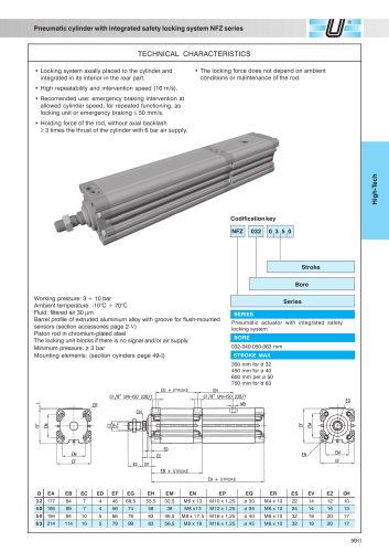
> Instructions for the connection of the clamp to its energy source Connect the sensor of the clamp to its electric supply unit. Then connect the pneumatic tube by means of suitable pneumatic fi ttings according to the specifi cation below: LAGP series G1/8" fittings Operating pressure from 4 to 8 bar ELECTRIC FEATURES Supply voltage Supply current without load Rated operational Output logic Wale coniacts Wcro C Ml 2 1. Unscrew the screw of the connector 4. Close the cover and screw it 1. It is not necessary to remove the air supply 2. Unscrew the sensor's screw 4. Screw the sensor to its housing...
Open the catalog to page 2All UNIVER Group catalogs and technical brochures
 JLE
JLE5 Pages
 HZRS
HZRS2 Pages
 MP Clamping cylinders
3 Pages
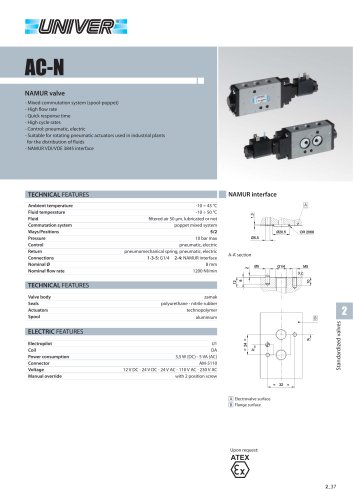 AC-N NAMUR valve
2 Pages
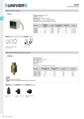 HZ9N
HZ9N1 Page
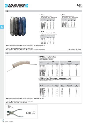 HE/HF tubes
1 Page
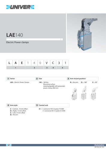 LAE140 Electric power clamps
4 Pages
 Modular Tooling System - GR8
52 Pages
 PRODUCT RANGE
44 Pages
 ATEX PRODUCT RANGE
14 Pages
 NEWS 2017-2018
32 Pages
 NEWS 2016
16 Pages
 PRODUCT OVERVIEW
228 Pages
 Product range
44 Pages
 ATEX Certified products
14 Pages
 NEWS 2017
32 Pages
 Valves
210 Pages
 ACCESSORIES
54 Pages
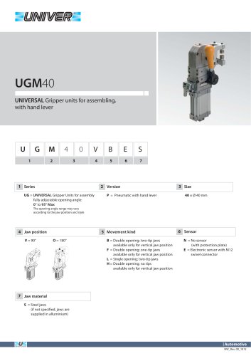
 UBH40_UNIVERSAL Power clamps
6 Pages
 PRODUCT RANGE
32 Pages
 LAGP605_Pneumatic power pivot
13 Pages
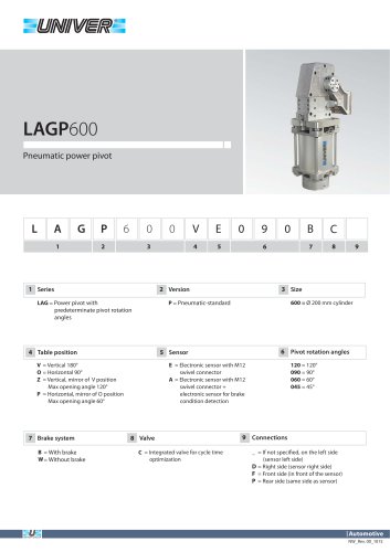 LAGP600_Pneumatic power pivot
13 Pages
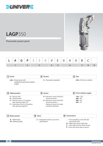 LAGP350_Pneumatic power pivot
13 Pages
 LAGP300_Pneumatic power pivot
13 Pages
 LAGP210_Pneumatic power pivot
13 Pages
 LAGP170_Pneumatic power pivot
13 Pages
 LAGP155_Pneumatic power pivot
13 Pages
 LAGP150_Pneumatic power pivot
13 Pages
 LAGP120_Pneumatic power pivot
13 Pages
 LAGP080_Pneumatic power pivot
13 Pages
 LAGP075_Pneumatic power pivot
13 Pages
 PRP1100_Marking units
3 Pages
 PRP0500_Marking Units
4 Pages
 PRP0050_Marking units
3 Pages
 PRP0025_Marking units
2 Pages
 LGP40_ Pneumatic Grippers
7 Pages
 LGP32_ Pneumatic Grippers
7 Pages
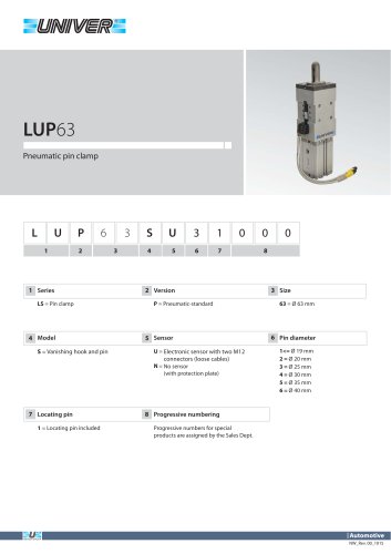 LUP63_Pneumatic pin clamp
2 Pages
 LSP60_Pneumatic pin clamp
3 Pages
 LSP50U_Pneumatic pin clamp
3 Pages
 LSP32_Pneumatic pin clamp
3 Pages
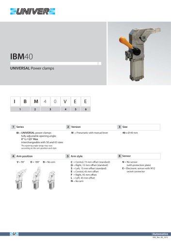 IBM40_UNIVERSAL Power clamps
6 Pages
 IBP40_UNIVERSAL Power clamps
6 Pages
 UBH63_UNIVERSAL Power clamps
6 Pages
 UBM40_UNIVERSAL Power clamps
6 Pages
 UBM50_UNIVERSAL Power clamps
10 Pages
 UBM63_UNIVERSAL Power clamps
10 Pages
 UBM80_UNIVERSAL Power clamps
10 Pages
 UBP32_UNIVERSAL Power clamps
4 Pages
 UBP50_UNIVERSAL Power clamps
6 Pages
 UBP63_UNIVERSAL Power clamps
6 Pages
 UBP80_UNIVERSAL Power clamps
8 Pages
 UBQ40_UNIVERSAL Power clamps
8 Pages
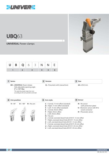 UBQ63_UNIVERSAL Power clamps
6 Pages
 UBT40_UNIVERSAL Power clamps
6 Pages
 Product Overview
228 Pages
 HIGH TECH
75 Pages
 CYLINDERS
67 Pages
 AUTOMOTIVE DIVISION
24 Pages
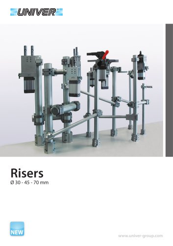 RISERS
4 Pages
 LGP32-40 Pneumatic Grippers
16 Pages
 GR8-Modular Tooling System
44 Pages
 M series
1 Page
 PIN CLAMPS
2 Pages
 CLAMPS
2 Pages
 AIR TREATMENT
14 Pages
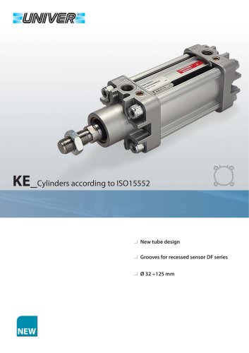 KE_Cylinders according to ISO 15552
10 Pages
 HZE_Additional components
4 Pages
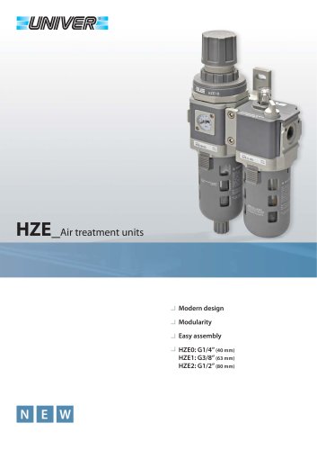
 HZE_Air treatment units
14 Pages
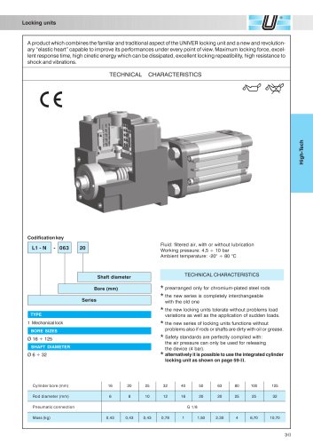 L1/L6_Locking unit for cylinders
6 Pages
 HZE_Air treatment units
12 Pages
 fittings
36 Pages
 PS_COMBOBOX valves
12 Pages
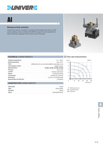 AI_Miniature limit switches
4 Pages
 CH_2/2 - 3/2 G1/8 poppet valves
4 Pages
 A_15 mm Microvalves
6 Pages
 B10_Nanovalvole 10 mm ISO 15218
2 Pages
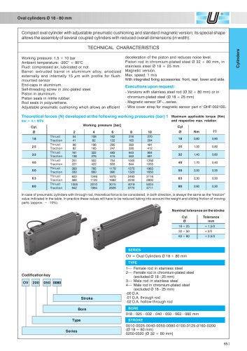 OV_Oval cylinders Ø 18-80 mm
5 Pages
 BE/BE12_ISO 5599/1 Valves
12 Pages
 Rodless cylinders Ø 16-50 mm
12 Pages
 Rotary actuators Ø 32-125 mm
3 Pages


- Rototherm valve
- Piping
- Rototherm control valve
- Rototherm tank
- Rototherm ball valve
- Rototherm cylinder
- Rototherm pneumatic valve
- Pneumatic fitting
- Rototherm actuator
- Metal fitting
- Plastic hose
- Rototherm shut-off valve
- Rototherm linear actuator
- Quick coupling
- Nickel-plated brass fitting
- Elbow fitting
- Rototherm ISO valve
- Rototherm clamping
- Rototherm pressure regulator