- Catalogs
- UNIVER Group
- OV_Oval cylinders Ø 18-80 mm
OV_Oval cylinders Ø 18-80 mm
1 /5Pages
OV_Oval cylinders Ø 18-80 mm
1 /5Pages
Catalog excerpts
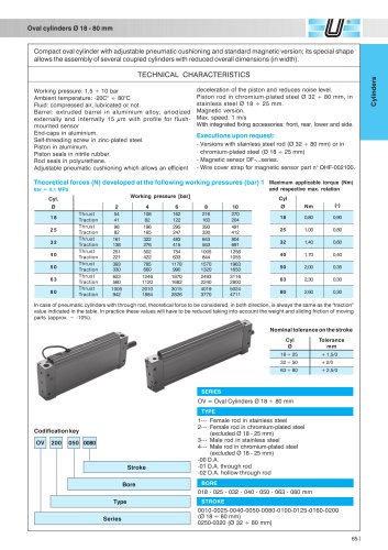
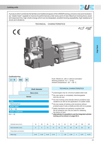
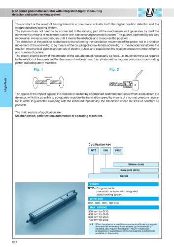
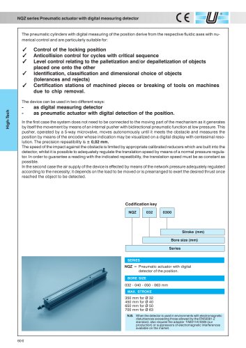
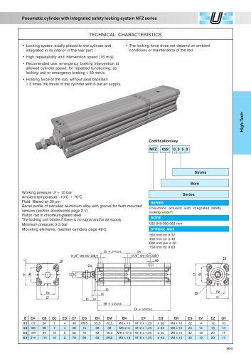
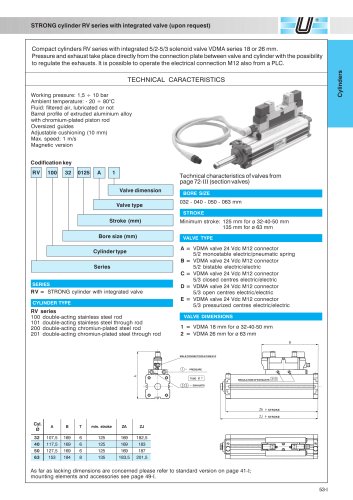
65-I Cylinders Cyl. Ø 2 4 6 8 10 18 Thrust 54 108 162 216 270 Traction 41 82 122 163 204 25 Thrust 98 196 295 393 491 Traction 82 165 247 330 412 32 Thrust 161 322 483 643 804 Traction 138 276 415 553 691 40 Thrust 251 502 754 1005 1256 Traction 221 422 633 844 1055 50 Thrust 393 785 1178 1570 1963 Traction 330 660 990 1320 1650 63 Thrust 623 1246 1870 2493 3116 Traction 560 1120 1682 2240 2800 80 Thrust 1005 2010 3015 4019 5024 Traction 942 1884 2826 3770 4711 Oval cylinders Ø 18 - 80 mm Compact oval cylinder with adjustable pneumatic cushioning and standard magnetic version; its special shape allows the assembly of several coupled cylinders with reduced overall dimensions (in width). Working pressure: 1,5 ÷ 10 bar Ambient temperature: -20C° ÷ 80°C Fluid: compressed air, lubricated or not. Barrel: extruded barrel in aluminium alloy, anodized externally and internally 15 ìm with profile for flushmounted sensor End-caps in aluminium. Self-threading screw in zinc-plated steel. Piston in aluminium. Piston seals in nitrile rubber. Rod seals in polyurethane. Adjustable pneumatic cushioning which allows an efficient TECHNICAL CHARACTERISTICS deceleration of the piston and reduces noise level. Piston rod in chromium-plated steel Ø 32 ÷ 80 mm, in stainless steel Ø 18 ÷ 25 mm. Magnetic version. Max. speed: 1 m/s With integrated fixing accessories: front, rear, lower and side. Executions upon request: - Versions with stainless steel rod (Ø 32 ÷ 80 mm) or in chromium-plated steel (Ø 18 ÷ 25 mm) - Magnetic sensor DF-...series. - Wire cover strap for magnetic sensor part n° DHF-002100. In case of pneumatic cylinders with through rod, theoretical force to be considered, in both direction, is always the same as the "traction" value indicated in the table. In practice these values will have to be reduced taking into account the weight and sliding friction of moving parts (approx. ~ -10%). Working pressure [bar] Theoretical forces (N) developed at the following working pressures (bar) 1 bar = 0,1 MPa Maximum applicable torque (Nm) and respective max. rotation Cyl Ø Nm (°) 18 0,80 0,90 25 1,00 0,80 32 1,40 0,60 40 1,70 0,40 50 2,00 0,35 63 2,30 0,30 80 2,60 0,30 Codification key Stroke Bore OV 200 050 0080 Type Series SERIES OV = Oval Cylinders Ø 18 ÷ 80 mm TYPE 1--- Female rod in stainless steel 2--- Female rod in chromium-plated steel (excluded Ø 18 - 25 mm) 3--- Male rod in stainless steel 4--- Male rod in chromium-plated steel (excluded Ø 18 - 25 mm) -00 D.A. -01 D.A. through rod -02 D.A. hollow through rod BORE 018 - 025 - 032 - 040 - 050 - 063 - 080 mm STROKE 0010-0025-0040-0050-0080-0100-0125-0160-0200 (Ø 18 ÷ 80 mm) 0250-0320 (Ø 32 ÷ 80 mm) Nominal tolerance on the stroke 18 ÷ 25 + 1,5/0 32 ÷ 50 + 2/0 63 ÷ 80 + 2,5/0 Cyl Tolerance Ø mm
Open the catalog to page 1All UNIVER Group catalogs and technical brochures
 JLE
JLE5 Pages
 HZRS
HZRS2 Pages
 MP Clamping cylinders
3 Pages
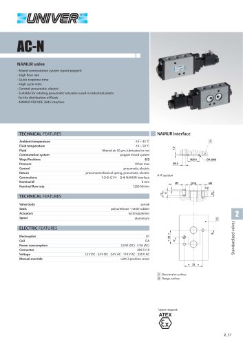 AC-N NAMUR valve
2 Pages
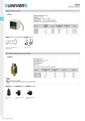 HZ9N
HZ9N1 Page
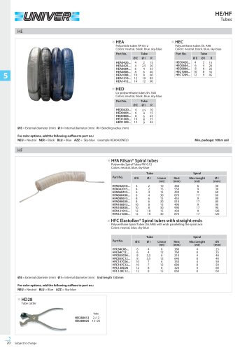 HE/HF tubes
1 Page
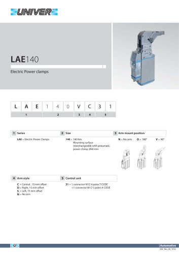 LAE140 Electric power clamps
4 Pages
 Modular Tooling System - GR8
52 Pages
 PRODUCT RANGE
44 Pages
 ATEX PRODUCT RANGE
14 Pages
 NEWS 2017-2018
32 Pages
 NEWS 2016
16 Pages
 PRODUCT OVERVIEW
228 Pages
 Product range
44 Pages
 ATEX Certified products
14 Pages
 NEWS 2017
32 Pages
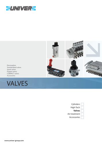 Valves
210 Pages
 ACCESSORIES
54 Pages
 UBH40_UNIVERSAL Power clamps
6 Pages
 PRODUCT RANGE
32 Pages
 LAGP605_Pneumatic power pivot
13 Pages
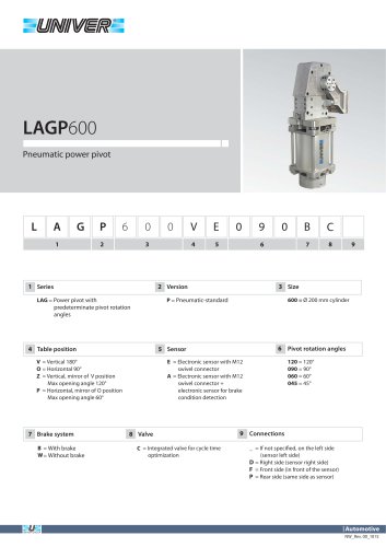 LAGP600_Pneumatic power pivot
13 Pages
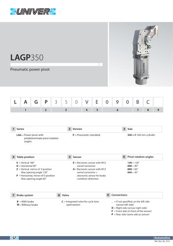 LAGP350_Pneumatic power pivot
13 Pages
 LAGP300_Pneumatic power pivot
13 Pages
 LAGP210_Pneumatic power pivot
13 Pages
 LAGP170_Pneumatic power pivot
13 Pages
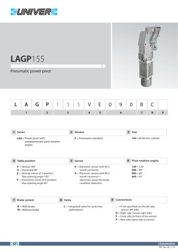 LAGP155_Pneumatic power pivot
13 Pages
 LAGP150_Pneumatic power pivot
13 Pages
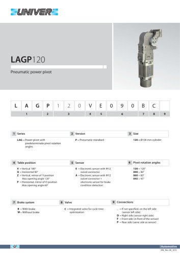 LAGP120_Pneumatic power pivot
13 Pages
 LAGP080_Pneumatic power pivot
13 Pages
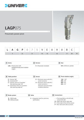 LAGP075_Pneumatic power pivot
13 Pages
 PRP1100_Marking units
3 Pages
 PRP0500_Marking Units
4 Pages
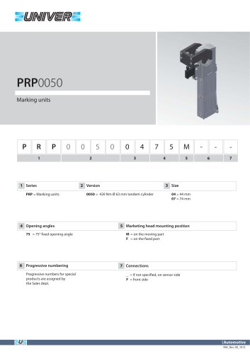 PRP0050_Marking units
3 Pages
 PRP0025_Marking units
2 Pages
 LGP40_ Pneumatic Grippers
7 Pages
 LGP32_ Pneumatic Grippers
7 Pages
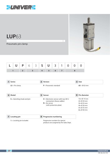 LUP63_Pneumatic pin clamp
2 Pages
 LSP60_Pneumatic pin clamp
3 Pages
 LSP50U_Pneumatic pin clamp
3 Pages
 LSP32_Pneumatic pin clamp
3 Pages
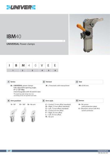 IBM40_UNIVERSAL Power clamps
6 Pages
 IBP40_UNIVERSAL Power clamps
6 Pages
 UBH63_UNIVERSAL Power clamps
6 Pages
 UBM40_UNIVERSAL Power clamps
6 Pages
 UBM50_UNIVERSAL Power clamps
10 Pages
 UBM63_UNIVERSAL Power clamps
10 Pages
 UBM80_UNIVERSAL Power clamps
10 Pages
 UBP32_UNIVERSAL Power clamps
4 Pages
 UBP50_UNIVERSAL Power clamps
6 Pages
 UBP63_UNIVERSAL Power clamps
6 Pages
 UBP80_UNIVERSAL Power clamps
8 Pages
 UBQ40_UNIVERSAL Power clamps
8 Pages
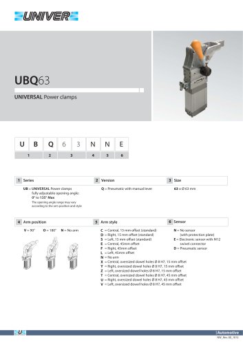 UBQ63_UNIVERSAL Power clamps
6 Pages
 UBT40_UNIVERSAL Power clamps
6 Pages
 Product Overview
228 Pages
 HIGH TECH
75 Pages
 CYLINDERS
67 Pages
 AUTOMOTIVE DIVISION
24 Pages
 RISERS
4 Pages
 LGP32-40 Pneumatic Grippers
16 Pages
 GR8-Modular Tooling System
44 Pages
 M series
1 Page
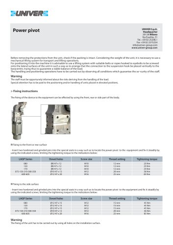 POWER PIVOTS
2 Pages
 PIN CLAMPS
2 Pages
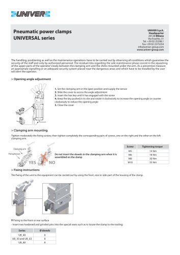 CLAMPS
2 Pages
 AIR TREATMENT
14 Pages
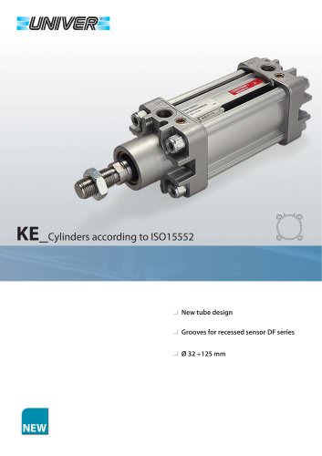 KE_Cylinders according to ISO 15552
10 Pages
 HZE_Additional components
4 Pages
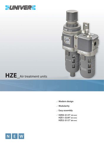
 HZE_Air treatment units
14 Pages
 L1/L6_Locking unit for cylinders
6 Pages
 HZE_Air treatment units
12 Pages
 fittings
36 Pages
 PS_COMBOBOX valves
12 Pages
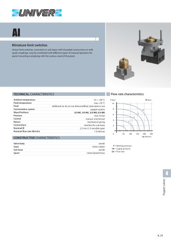 AI_Miniature limit switches
4 Pages
 CH_2/2 - 3/2 G1/8 poppet valves
4 Pages
 A_15 mm Microvalves
6 Pages
 B10_Nanovalvole 10 mm ISO 15218
2 Pages
 BE/BE12_ISO 5599/1 Valves
12 Pages
 Rodless cylinders Ø 16-50 mm
12 Pages
 Rotary actuators Ø 32-125 mm
3 Pages


- Rototherm valve
- Piping
- Fitting
- Rototherm control valve
- Rototherm tank
- Rototherm ball valve
- Rototherm pneumatic valve
- Pneumatic fitting
- Rototherm actuator
- Metal fitting
- Plastic hose
- Rototherm shut-off valve
- Rototherm linear actuator
- Quick coupling
- Nickel-plated brass fitting
- Elbow fitting
- Rototherm ISO valve
- Rototherm clamping
- Rototherm pressure regulator