- Catalogs
- UNIVER Group
- HIGH TECH


HIGH TECH

HIGH TECH
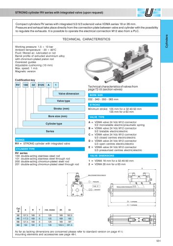
- Telescopic Pneumatic Cylinders: Available in diameters Ø 25 ÷ 63 mm with 2-3 stages, and Ø 32 ÷ 63 mm with integrated VDMA valve BD series.
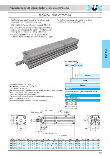
- Pneumatic Cylinders with Safety Features: Models include integrated safety locking systems and measuring detectors.
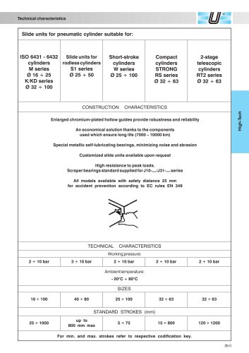
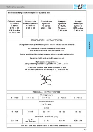
- Slide Units: Designed for various cylinder types with different bore sizes and series.
- Designed for rods Ø 6 ÷ 32 mm and cylinders Ø 16 ÷ 125 mm.
- Features include maximum locking force, excellent response time, and high resistance to shock and vibrations.
- Technical characteristics include a working pressure of 4.5 ÷ 10 bar and an ambient temperature range of -20° ÷ 80°C.
- Details on static and dynamic locking forces, response time, and repeatability of locking points.
- Resistance to vibration and shock resistance values are provided.
- Available in series S1, S5, and VL1, with extruded aluminium profiles and strokes up to 6 meters.
- Features include high translation speeds, integrated guides, and various carriage types.
- Technical characteristics cover working pressure, ambient temperature, and fluid requirements.
- Guidelines for controlling kinetic energy dissipation to avoid compromising cylinder life.
- Methods for selecting appropriate cushioning based on load and speed.
- Options for magnetic versions, slide units, and locking units are available upon request.
- End-caps offer various supply port configurations, and the system includes pneumatic adjustable cushions and mechanical rubber shock absorbers.
The cylinders operate at a working pressure of 3-10 bar and can function in ambient temperatures from -20°C to +80°C. They use filtered air, with or without lubrication, and have a maximum translation speed of 3 m/s. The pneumatic sealing system uses an elastomer stripseal reinforced with Kevlar for dimensional stability.
Guidelines for calculating inertia forces and corresponding torques, emphasizing the importance of controlling kinetic energy dissipation to prevent damage to the cylinder. Methods for cushioning, including pneumatic and hydraulic options, are suggested to manage impact speed and moving mass.
Recommendations include using oscillating mounting brackets when the cylinder is mounted on external rigid guides to isolate the cylinder from the structure. The document advises against using the cylinder in high-stress applications and highlights the need to reduce load under dynamic conditions.
Various accessories are available, including magnetic sensors, locking units, and mounting plates. The magnetic option for the S1 series is standard for Ø 16 mm and available upon request for larger sizes. The S5 series requires a separate magnetic switch mounting rail.
Includes detailed tables with dimensions, mass, and force values for different cylinder sizes and configurations. A codification key for identifying specific cylinder models based on their features is provided.
Pneumatic actuators with integrated safety locking systems are suitable for emergency braking and repeated functioning at cylinder speeds ≤ 50 mm/s. The holding force of the rod is at least three times the thrust of the cylinder with a 6 bar air supply. The locking force is independent of ambient conditions or rod maintenance.
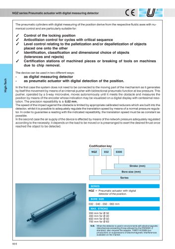
Pneumatic actuators feature digital measuring detectors for applications such as control of locking positions, anticollision control, and level control in palletization. The system can function as a digital measuring detector or a pneumatic actuator with digital position detection. Precision repeatability is ± 0.02 mm, with a maximum speed of 0.2 m/s for the detector and 0.8 m/s for the actuator.
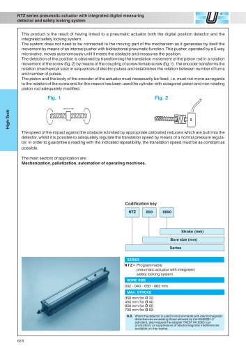
The NQZ series includes bore sizes of 032, 040, 050, and 063 mm, with maximum strokes of 350 mm for ø 32, 450 mm for ø 40, 650 mm for ø 50, and 700 mm for ø 63. The NTZ series is a programmable pneumatic actuator with an integrated safety locking system.
The actuators operate with a power supply of 5 Vdc, with output levels "L" < 0.5V and "H" Vdc. They have a limit frequency of 60 Khz, impedance of 2 Kohm, and a current consumption of 40 mA max. The resolution is ± 0.01 pulses/turn, and the working temperature range is -10° to +70°C.
Main applications include mechanization, palletization, and automation of operating machines. The actuators are equipped with mounting accessories and flush-mounted magnetic sensors.
Includes detailed technical specifications, theoretical forces for different cylinder sizes, and overall dimensions. Information on the functioning of the locking unit and necessary conditions for optimal performance is provided.
Catalog excerpts

Locking units A product which combines the familiar and traditional aspect of the UNIVER locking unit and a new and revolution- ary "elastic heart" capable to improve its performances under every point of view. Maximum locking force, excel- lent response time, high cinetic energy which can be dissipated, excellent locking repeatibility, high resistance to TECHNICAL CHARACTERISTICS Shaft diameter BORE SIZES SHAFT DIAMETER Fluid: filtered air, with or without lubrication TECHNICAL CHARACTERISTICS * prearranged only for chromium-plated steel rods * the new series is completely interchangeable *...
Open the catalog to page 2
Technical characteristics A spring in special steel, developed together with FEA (Finite Element Analysis) and with the assistance of the most advanced CAD technics, constitutes the heart of this new locking unit which, in addition to the excellent locking capacity and repeatibility, enable a soft braking of the moved masses. Main performances and characteristics: * For release pressure values under 4 bar, the reaction of the locking unit cannot be foreseen. Braking distance In some applications, it could be necessary to know the piston rod stroke between the reception of an emergency This value...
Open the catalog to page 3
Locking units for 0 16 - 20 - 25 mm ISO microcylinders Additional length to the standard rod Locking unit for compact cylinders STRONG 0 32 - 63 mm Fixing screws Additional length to standard rod with ISO protrusion
Open the catalog to page 4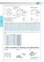
Locking units for ISO cylinders 0 32 + 125 Reduced protrusion Pneumatic lock Additional length to the standard rod Screw with hexagonal head UNI 5739 and washer UNI 6592 for assembling locking unit to ISO .other examples of locking unit applications Chromium-plated shaft
Open the catalog to page 5
L6 series locking unit for rodless cylinders Locking unit The UNIVER locking unit for rodless cylinders has been realized with the aim to stop the carriage in any point of its stroke and it is able to provide a good locking precision. It is possible to assemble it indifferently on either side of the carriage and its mechanical braking force may be further amplified by means of an additional pneumatic control. Fluid: filtered air, with or without lubrification Locking unit for S5 series Manual release Maximum locking force (N) Locking unit for VL1 series Manual release Maximum locking force (N)...
Open the catalog to page 6
Locking unit for S5 series Stroke Locking Fixing dimensions Locking unit for VL1 series Stroke Locking Fixing dimensions
Open the catalog to page 7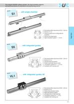
The original UNIVER rodless cylinder, the most versatile range for solving the problems of automation and positioning control S1 . . . with single chamber Extruded profile in aluminium Ø 16 ÷ 50 mm. Stroke to 5 m. Various supply port configurations available. Various carriage types. High translation speed 1 ÷ 3 m/s. Series S5 . . . with integrated guides Series VL1 Extruded profile in aluminium Ø 25 ÷ 50 mm. Stroke to 6 m. Flexible bearing system. Plastic bearings reduce noise. Translation speed 0,2 ÷ 1,5 m/s. Available with locking unit. . . . with integrated guides 90° Extruded profile in aluminium...
Open the catalog to page 8
Fluid: filtered air, with or without lubrication Standard strokes: up to 5 meters (0 16 mm) Min. speed required for regular translation: 7 20 mm/s. Carriage types: standard, medium, long, double medium Integrated guides: S5 series: round steel shafts VL1 series: steel foils at 90° External carriage slide: S5 series: with plastic sliding shoes VL1 series:with ball bearings Upon request - Magnetic version for S1 series (except for 0 16 magnetic version standard); for S5 series a special magnetic sensor holder extrusion DKS series is foreseen (section accessories page 6- ). - Magnetic sensor DH-series...
Open the catalog to page 9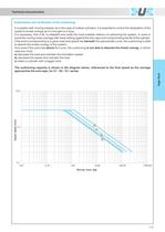
Technical characteristics Examination and verification of the cushioning In a system with moving masses, as in the case of rodless cylinders, it is essential to control the dissipation of the system's kinetic energy as it is brought to a stop. It is necessary, first of all, to establish and verify the most suitable method of cushioning the system, in order to avoid the moving mass (carriage with load) striking against the end-caps and compromising the life of the cylinder. If the point corresponding to a given load and speed lies beneath the appropriate curve, the cushioning is able to absorb...
Open the catalog to page 10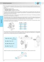
If it is not possible to absorb the kinetic energy with the cushioned end-caps and modify the parameters (a-b-c shown at page 11), an additional cushioning is necessary to reduce the load speed before the cylinder strikes the - a pneumatic cushion with electronic control; - a hydraulic cushion, available on the market. The mass movement generates loads to the cylinder, connected both to the weight forces (load values are constant) and to the inertia forces which originate in the acceleration or deceleration phases of the piston at the A typical fatigue stress arises in which the load value affects...
Open the catalog to page 11
Codification key for rodless cylinders "S" Series 0 16 -s- 50 mm Right end-cap supply port (dx) Left end-cap supply port (sx) Carriage type S5 = Integrated guides/plastic bearings CARRIAGE TYPE LEFT END-CAP SUPPLY PORT 0 = No supply port (when both chambers are supplied from the right end-cap) 1 = Side supply port * 2 = Bottom supply port * 3 = Rear supply port * RIGHT END-CAP SUPPLY PORT 1 = Side supply port (twin 0 16 mm) 2 = Bottom supply port * 3 = Rear supply port (twin 0 16 mm) 4 = Both chambers supplied from the right end-cap BORE SIZE M = Magnetic version standard for 0 16 mm, upon request...
Open the catalog to page 12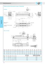
Rodless cylinders with standard carriage - 6 fixing holes cushion needles Mass (kg) Weight increase (kg) per Cyl0 AU AV AW AX AY AZ_at "0" stroke_additional 100 mm stroke
Open the catalog to page 13
Values of the static load; please note that under dynamic conditions the load must be reduced due to the effects associated with the speed. The torque is the prod uct of load (Newton) per arm (meters), i.e. the distance between the center of gravity of the load and the longitudinal axis of the piston (technical characteristics see page 11-12- ). Bending moment Bending moment Standard carriage Medium carriage Long carriage ♦ It is not advisable to use the cylinder in applications with high stress. Medium carriage - 6 fixing holes for cylinders 0 25 4- 50 mm Long carriage -10 fixing holes for cylinders...
Open the catalog to page 14All UNIVER Group catalogs and technical brochures
 JLE
JLE5 Pages
 HZRS
HZRS2 Pages
 MP Clamping cylinders
3 Pages
 AC-N NAMUR valve
2 Pages
 HZ9N
HZ9N1 Page
 HE/HF tubes
1 Page
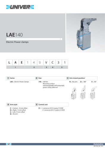 LAE140 Electric power clamps
4 Pages
 Modular Tooling System - GR8
52 Pages
 PRODUCT RANGE
44 Pages
 ATEX PRODUCT RANGE
14 Pages
 NEWS 2017-2018
32 Pages
 NEWS 2016
16 Pages
 PRODUCT OVERVIEW
228 Pages
 Product range
44 Pages
 ATEX Certified products
14 Pages
 NEWS 2017
32 Pages
 Valves
210 Pages
 ACCESSORIES
54 Pages
 UBH40_UNIVERSAL Power clamps
6 Pages
 PRODUCT RANGE
32 Pages
 LAGP605_Pneumatic power pivot
13 Pages
 LAGP600_Pneumatic power pivot
13 Pages
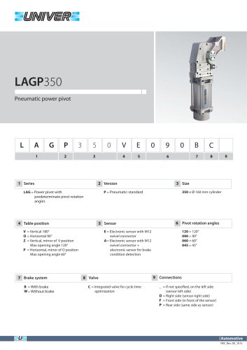 LAGP350_Pneumatic power pivot
13 Pages
 LAGP300_Pneumatic power pivot
13 Pages
 LAGP210_Pneumatic power pivot
13 Pages
 LAGP170_Pneumatic power pivot
13 Pages
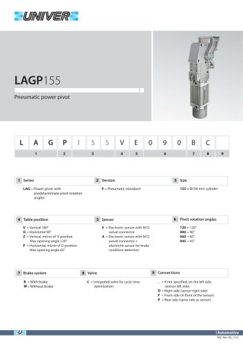 LAGP155_Pneumatic power pivot
13 Pages
 LAGP150_Pneumatic power pivot
13 Pages
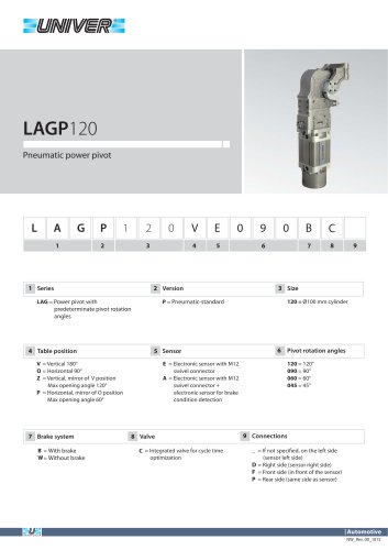 LAGP120_Pneumatic power pivot
13 Pages
 LAGP080_Pneumatic power pivot
13 Pages
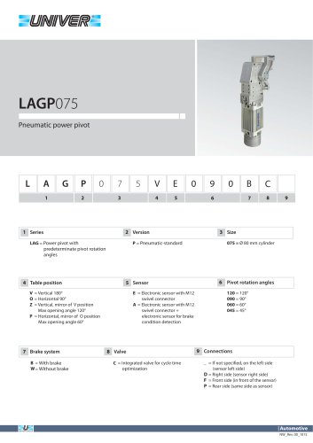 LAGP075_Pneumatic power pivot
13 Pages
 PRP1100_Marking units
3 Pages
 PRP0500_Marking Units
4 Pages
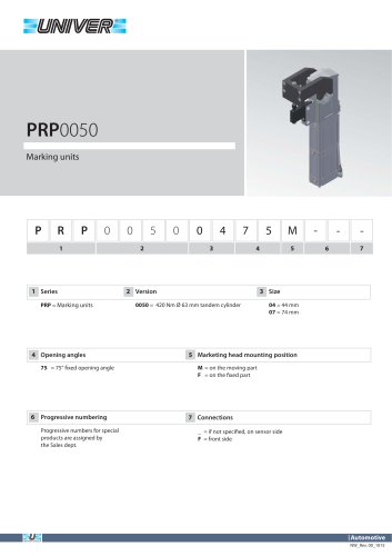 PRP0050_Marking units
3 Pages
 PRP0025_Marking units
2 Pages
 LGP40_ Pneumatic Grippers
7 Pages
 LGP32_ Pneumatic Grippers
7 Pages
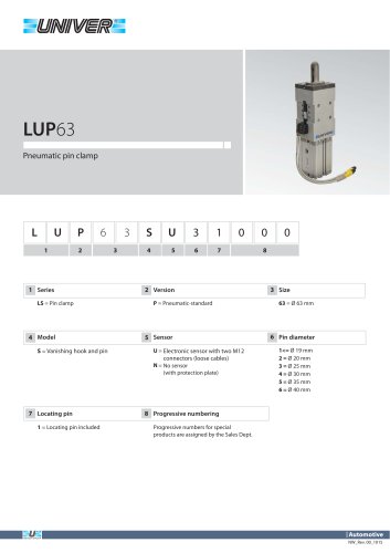 LUP63_Pneumatic pin clamp
2 Pages
 LSP60_Pneumatic pin clamp
3 Pages
 LSP50U_Pneumatic pin clamp
3 Pages
 LSP32_Pneumatic pin clamp
3 Pages
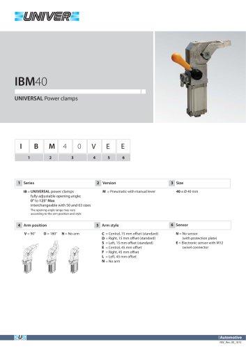 IBM40_UNIVERSAL Power clamps
6 Pages
 IBP40_UNIVERSAL Power clamps
6 Pages
 UBH63_UNIVERSAL Power clamps
6 Pages
 UBM40_UNIVERSAL Power clamps
6 Pages
 UBM50_UNIVERSAL Power clamps
10 Pages
 UBM63_UNIVERSAL Power clamps
10 Pages
 UBM80_UNIVERSAL Power clamps
10 Pages
 UBP32_UNIVERSAL Power clamps
4 Pages
 UBP50_UNIVERSAL Power clamps
6 Pages
 UBP63_UNIVERSAL Power clamps
6 Pages
 UBP80_UNIVERSAL Power clamps
8 Pages
 UBQ40_UNIVERSAL Power clamps
8 Pages
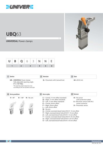 UBQ63_UNIVERSAL Power clamps
6 Pages
 UBT40_UNIVERSAL Power clamps
6 Pages
 Product Overview
228 Pages
 CYLINDERS
67 Pages
 AUTOMOTIVE DIVISION
24 Pages
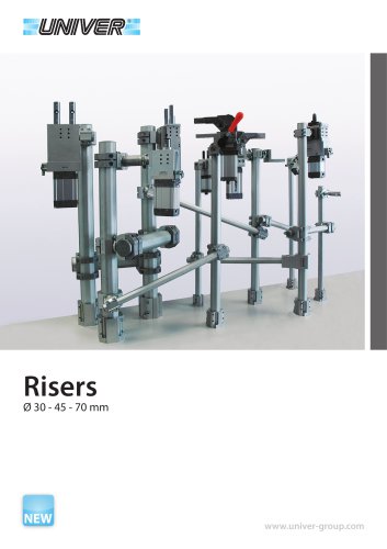 RISERS
4 Pages
 LGP32-40 Pneumatic Grippers
16 Pages
 GR8-Modular Tooling System
44 Pages
 M series
1 Page
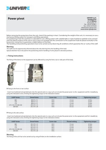 POWER PIVOTS
2 Pages
 PIN CLAMPS
2 Pages
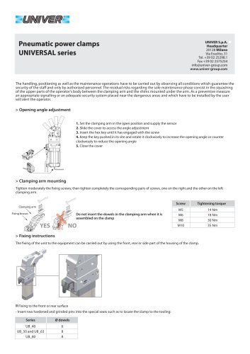 CLAMPS
2 Pages
 AIR TREATMENT
14 Pages
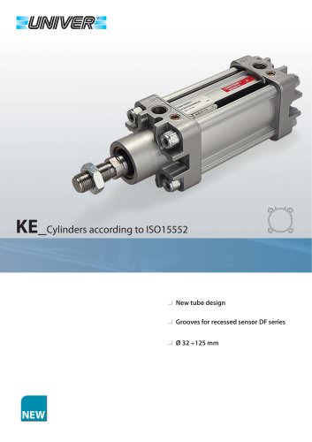 KE_Cylinders according to ISO 15552
10 Pages
 HZE_Additional components
4 Pages
 HZE_Air treatment units
14 Pages
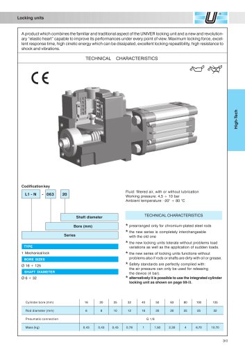 L1/L6_Locking unit for cylinders
6 Pages
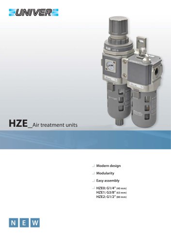 HZE_Air treatment units
12 Pages
 fittings
36 Pages
 PS_COMBOBOX valves
12 Pages
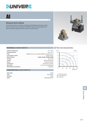 AI_Miniature limit switches
4 Pages
 CH_2/2 - 3/2 G1/8 poppet valves
4 Pages
 A_15 mm Microvalves
6 Pages
 B10_Nanovalvole 10 mm ISO 15218
2 Pages
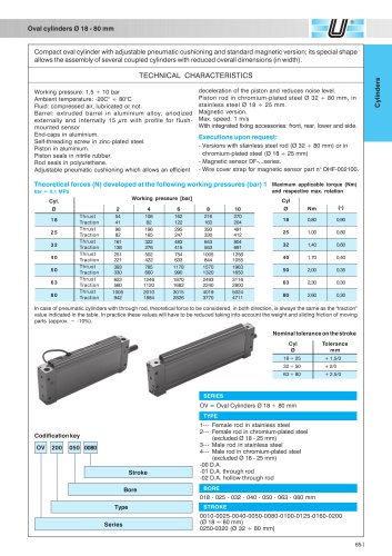 OV_Oval cylinders Ø 18-80 mm
5 Pages
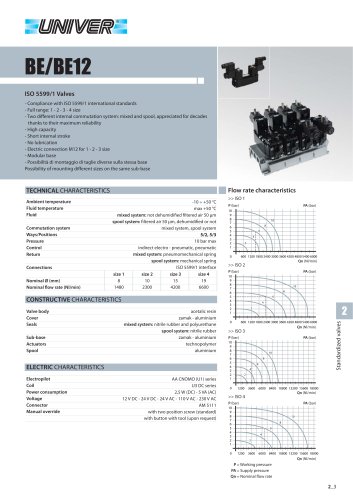 BE/BE12_ISO 5599/1 Valves
12 Pages
 Rodless cylinders Ø 16-50 mm
12 Pages
 Rotary actuators Ø 32-125 mm
3 Pages