
- Catalogs
- Unitronics
- US7-x10-T42


US7-x10-T42

US7-x10-T42
Unitronics' UniStream® Built-in series are all-in-one programmable controllers that integrate a CPU, HMI panel, and built-in I/Os. The series includes two versions: UniStream Built-in and UniStream Built-in Pro, which differ in features such as system memory, audio jack, video support, web server, and SQL client capabilities.
- Resistive color touch-screens with a comprehensive graphic library for HMI design.
- Features include built-in trends, gauges, auto-tuned PID, data tables, sampling, and recipes.
- UniApps™ for data access, monitoring, troubleshooting, and debugging.
- Multi-level password protection and built-in alarm systems.
- Built-in I/O configurations vary by model, with options for local and remote I/O expansion.
- Communication ports include Ethernet, USB host, and Mini-B USB device ports, with additional serial and CANbus ports available via modules.
- Supports various communication protocols including CANopen, MODBUS, and EtherNetIP.
- Ensure proper ventilation and avoid installation in areas with excessive dust, moisture, or heat.
- Maintain a 10mm space between the device and enclosure walls.
- Install at a maximum distance from high-voltage cables and power equipment.
- Includes a PLC+HMI controller, mounting brackets, panel mounting seal, power terminal block, I/O terminal blocks (for models with built-in I/Os), and a battery.
- Designed for SELV/PELV/Class 2 environments with double insulation power supplies.
- Use over-current protection and ensure all wiring is performed with power off.
- Follow specific wiring guidelines to avoid electromagnetic interference.
- The battery is necessary for preserving RTC and system data during power off.
- Ensure proper precautions against Electro-Static Discharge (ESD) during servicing.
- Dispose of the product and battery according to local and national regulations.
- Installation should be performed by qualified personnel only.
Ensure conductors for 3- or 4-wire RTDs are of the same type, width, and length to maintain accuracy. For 4-wire RTDs, use a 3-wire cable and leave the unused wire unconnected and short.
Use a limited current source or a current limiting device to prevent fire or damage. Relay outputs are in two isolated groups: O0-O3 (CM3) and O4-O7 (CM4). To extend relay contact life and protect against reverse EMF, use a clamping diode for DC loads and an RC snubber circuit for AC loads.
Requires an external 24VDC power supply. Connect +VO and 0VO terminals as shown in the figure, with O0-O9 sharing common return 0VO.
Outputs are not isolated and can be set to voltage or current mode independently. Mode configuration must match the wiring setup in the software application. CM5 is internally connected to 0V; avoid external connections to minimize EMI pickup.
Follow the provided Installation Guides. Turn off power and prevent ESD when connecting or disconnecting modules.
Disconnect power supply. Remove wiring and devices as per installation guide. Unscrew and remove mounting brackets carefully.
Information is subject to change without notice. Provided "as is" without warranty; Unitronics is not liable for errors or damages.
Catalog excerpts

Installation Guide UniStream® Built-in This guide provides basic installation information for specific UniStream® models with built-in I/O. Technical specifications may be downloaded from the Unitronics website. General Features Unitronics’ UniStream® Built-in series are PLC+HMI All-in-One programmable controllers that comprise a built-in CPU, an HMI panel, and built-in I/Os. The series is available in two versions: UniStream Built-in and UniStream Built-in Pro. Note that a model number that includes: • B5/C5 refers to UniStream Built-in B10/C10 refers to UniStream Built-in Pro. These models offer additional features, detailed below. ▪ Resistive Color Touch-screens ▪ Rich graphic library for HMI design Power Features ▪ Built-in Trends and Gauges, auto-tuned PID, data tables, data sampling, and Recipes ▪ UniApps™: Access & edit data, monitor, troubleshoot & debug and more – via HMI or remotely via VNC ▪ Security: Multi-level password protection ▪ Alarms: Built-in system, ANSI/ISA standards ▪ Built-in I/O configuration, varies according to model ▪ Local I/O via UAG-CX series I/O expansion adapters and standard UniStream Uni-I/O™ modules ▪ Remote I/O using UniStream Remote I/O or via EX-RC1 ▪ Built-in ports: 1 Ethernet, 1 USB host, 1 Mini-B USB device port ▪ Serial and CANbus ports may be added via UAC-CX modules ▪ Fieldbus: CANopen, CAN Layer2, MODBUS, EtherNetIP and more. Implement any serial RS232/485, TCP/IP, or CANbus third-party protocols via Message Composer ▪ Advanced: SNMP Agent/Trap, e-mail, SMS, modems, GPRS/GSM, VNC Client, FTP Server/Client Programming Software All-in-One software for hardware configuration, communications, and HMI /PLC applications, available as a free do
Open the catalog to page 1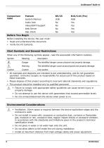
UniStream® Built-in Comparison table System Memory Audio Jack Video/RSTP Support Before You Begin Before installing the device, the user must: ▪ Read and understand this document. ▪ Verify the Kit Contents. Alert Symbols and General Restrictions When any of the following symbols appear, read the associated information carefully. Symbol The identified danger causes physical and property damage. Warning Caution The identified danger could cause physical and property damage. ▪ All examples and diagrams are intended to aid understanding, and do not guarantee operation. Unitronics accepts no responsibility...
Open the catalog to page 2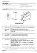
UniStream® Built-in Kit Contents ▪ 1 PLC+HMI controller ▪ 1 power terminal block ▪ 2 I/O terminal blocks (provided only with models comprising built-in I/Os) ▪ 1 panel mounting seal ▪ 2 panel supports (US7/US10 only) Product Diagram Front and Rear View 1 Screen Protection A plastic sheet attached to the screen for protection. Remove it during installation of the HMI Panel. Battery Cover The battery is supplied with the unit, but must be installed by the user. Power Supply Input Connection point for the controller power source. microSD Slot Supports standard microSD cards. Provides the interface...
Open the catalog to page 3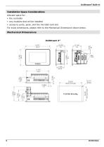
UniStream® Built-in Installation Space Considerations Allocate space for: ▪ the controller ▪ any modules that will be installed ▪ access to ports, jacks, and the microSD card slot For exact dimensions, please refer to the Mechanical Dimensions shown below. Mechanical Dimensions
Open the catalog to page 4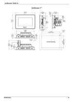
UniStream® Built-in
Open the catalog to page 5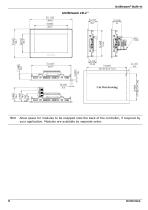
UniStream® Built-in Allow space for modules to be snapped onto the back of the controller, if required by your application. Modules are available by separate order.
Open the catalog to page 6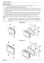
UniStream® Built-in Panel Mounting NOTE ▪ Mounting panel thickness must be less or equal to 5mm (0.2”). ▪ Ensure that the space considerations are met. 1. Prepare a panel cut-out according to the dimensions as shown in the previous section. 2. Slide the controller into the cut-out, ensuring that the Panel Mounting Seal is in place as shown below. 3. Push the mounting brackets into their slots on the sides of the panel as shown below. 4. Tighten the bracket screws against the panel. Hold the brackets securely against the unit while tightening the screws. The torque required is 0.35 N·m (3.1 in-lb)....
Open the catalog to page 7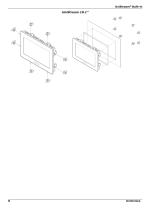
UniStream® Built-in
Open the catalog to page 8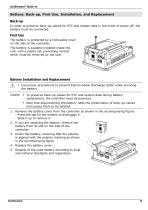
UniStream® Built-in Battery: Back-up, First Use, Installation, and Replacement Back-up In order to preserve back-up values for RTC and system data in the event of power off, the battery must be connected. First Use The battery is protected by a removable cover on the side of the controller. The battery is supplied installed inside the unit, with a plastic tab preventing contact which must be removed by the user. Battery Installation and Replacement ▪ Use proper precautions to prevent Electro-Static Discharge (ESD) while servicing the battery. Caution ▪ To preserve back-up values for RTC and system...
Open the catalog to page 9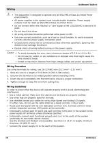
UniStream® Built-in Wiring ▪ This equipment is designed to operate only at SELV/PELV/Class 2/Limited Power environments. ▪ All power supplies in the system must include double insulation. Power supply outputs must be rated as SELV/PELV/Class 2/Limited Power. ▪ Do not connect either the ‘Neutral’ or ‘Line’ signal of the 110/220VAC to device’s 0V point. ▪ Do not touch live wires. ▪ All wiring activities should be performed while power is OFF. ▪ Use over-current protection, such as a fuse or circuit breaker, to avoid excessive currents into the power supply connection point. ▪ Unused points should...
Open the catalog to page 10
UniStream® Built-in ▪ Earthing the cables' shield: ➢ Keep shield connections as short as possible. Connect the cable shield to the earth of the system (preferably to the metal cabinet chassis). Note that the shield must be connected only at one end of the cable; it is recommended to earth the shield at the PLC-side. Ensure shield continuity when extending shielded cables. For detailed information, refer to the document System Wiring Guidelines, located in the Technical Library in the Unitronics’ website. Wiring the Power Supply The controller requires an external power supply. ▪ In the event...
Open the catalog to page 11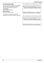
UniStream® Built-in The IOs for these models are arranged in three groups of fifteen points each, as shown in the figures to the right. Top groups Input connection points Bottom group Output connection points The function of certain I/Os may be adapted via wiring and software settings.
Open the catalog to page 12All Unitronics catalogs and technical brochures
 US7-x10-TA30
18 Pages
 US7-x10-RA28
18 Pages
 US7-x5-RA28
18 Pages
 US7-x5-T42
10 Pages
 US7-x10-R38
10 Pages
 US7-x5-R38
10 Pages
 US7-x10-T24
9 Pages
 US7-x5-T24
9 Pages
 US7-x10-TR22
9 Pages
 US7-x5-TR22
9 Pages
 US7-x10-B1
9 Pages
 US7-x5-B1
9 Pages
 Global Catalogue
24 Pages
Archived catalogs
 Global catalogue
13 Pages
 Vision 570 PLC + Color HMI
6 Pages
 M90/M91 PLC+HMI catalogue
11 Pages
 Jazz PLC+HMI catalogue
16 Pages


- IO module
- Servo-motor
- Analog I/O
- AC servo-motor
- Analog IO module
- Controller servomotor
- IP65 servomotor
- Remote IO module
- Ethernet IO module
- Ethernet programmable logic controller
- Fieldbus PLC
- Networked PLC
- RS485 programmable logic controller
- Compact programmable logic controller
- RS232 programmable controller
- Modular programmable logic controller
- Temperature I O module
- Analog inputs PLC