M91-2-R1
1 /3Pages
M91-2-R1
1 /3Pages
Catalog excerpts
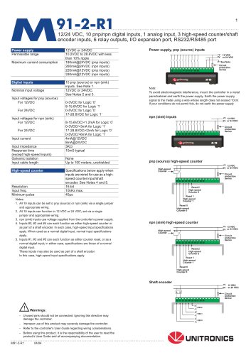
91-2-R112/24 VDC, 10 pnp/npn digital inputs, 1 analog input, 3 high-speed counter/shaft encoder inputs, 6 relay outputs, I/O expansion port, RS232/RS485 port Power supply Power supply, pnp (source) inputs protection device To avoid electromagnetic interference, mount the controller in a metal panel/cabinet and earth the power supply. Earth the power supply signal to the metal using a wire whose length does not exceed 10cm. If your conditions do not permit this, do not earth the power supply. pnp (source) high-speed counter H—Circuit protection device 1. All 10 Inputs can be set to pnp (source) or npn (sink) via a single jumper and appropriate wiring. 2. All 10 inputs can function in 12 VDC or 24 VDC; set via a single jumper and appropriate wiring. 3. npn (sink) inputs use voltage supplied from the controller’s power supply. 4. Inputs #0, #2 and #4 can each function as either high-speed counter or as part of a shaft encoder. In each case, high-speed input specifications apply. When used as a normal digital input, normal input specifications apply. 5. Inputs #1, #3 and #5 can each function as either counter reset, or as a normal digital input; in either case, specifications are those of a normal digital input. These inputs may also be used as part of a shaft encoder. In this case, high-speed input specifications apply. Reset 1 High-speed Counter 1 Reset 0 High-speed Counter 0 npn (sink) high-speed counter protection device Reset 0 High-speed Counter 0 - Unused pins should not be connected. Ignoring this directive may damage the controller. - Improper use of this product may severely damage the controller. - Refer to the controller's User Guide regarding wiring considerations. - Before using this product, it is the responsibility of the user to read the product's User Guide and all accompanying documentation. Shaft encoder
Open the catalog to page 1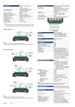
Digital outputs Output type Type of relay Output current Max, frequency Contact protection Relay Outputs The analog value can also Indicate when the Input is functioning out of range. If an analog Input deviates above the permissible range, its value will be 1024. Voltage connection Current connections 6 relay outputs, 230VAC/ 12/24VDC SPST-NO relay Takamisawa (Fujitsu) JY-12H-K, or NAIS (Matsushita) JQ1A-12V or OMRON G6B-1114P-12VDC by relay 5A max. (resistive load) lAmax. (inductive load) External precautions required RS232/RS485 is determined by jumper settings and wiring, as described in...
Open the catalog to page 2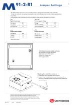
The tables below show how to set a specific jumper to change the functionality of the controller. To open the controller and access the jumpers, refer to the directions at the end of these specifications. Incompatible jumper settings and wiring connections may severely damage the controller. Digital inputs type Power supply voltage Digital inputs voltage Analog input type •Default factory setting In this figure, the jumper settings will cause the controller to function as follows: Digital inputs: npn, 24VDC inputs Analog input: Voltage input Power supply: 24VDC Unitronics reserves the right to...
Open the catalog to page 3All Unitronics (1989)(R"G) LTD catalogs and technical brochures
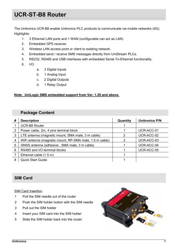 UCR-ST-B8 Router
7 Pages
 Unitronics 4G Routers
3 Pages
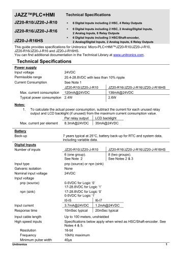 JAZZ™PLC+HMI
4 Pages
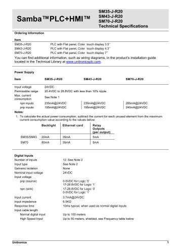 Samba™PLC+HMI™
5 Pages
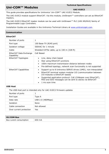 Uni-COM™ Modules
3 Pages
 EtherCAT
2 Pages
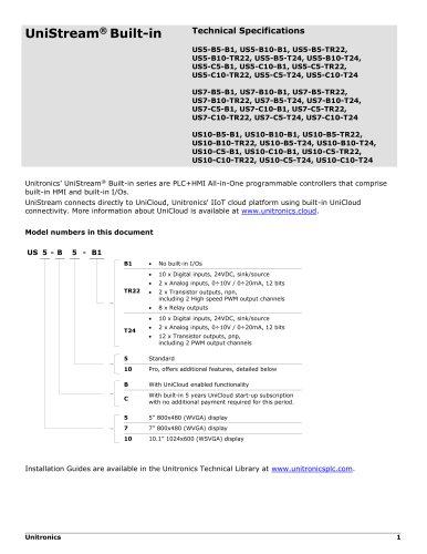 UniStream® Built-in
9 Pages
- Cloud-based software
- Industrial software
- Interface software
- Programmable logic controller
- Programming software
- Communication router with VPN
- Cellular communication router
- Ethernet programmable logic controller
- Networked PLC
- PLC software
- 4G LTE communication router
- Multi-axis positioning controller
- All-in-one software
- IIOT software
- High-speed motion controller
- AC motion controller
- Modbus TCP communication router
- PLC motion controller
- Three-phase motion controller