Catalog excerpts

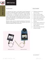
INDICATING TEMPERATURE CONTROLS AND THERMOMETERS features • Simple adjustment and control • Rugged construction for demanding applications • Improve efficiency with best-in-class repeatability • Meet environment requirements with enclosure design options • Match process requirements with an assortment of available ranges
Open the catalog to page 1
For applications that require a visual display of process temperature and set point, the 800 Series offers a highly readable four inch setting/ indication scale. It is available in two versions: a Lexan® enclosure for enclosure type 1 or 4 applications (with option M300), and with Lexan® window and epoxy-coated aluminum enclosure for Div. 1 explosion proof applications. For temperature indication only, the T800 thermometer incorporates the same performance and construction features of the 800 Series. 800 Series models control and indicate the temperature of food service appliances, ovens,...
Open the catalog to page 2
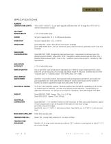
specifications Ambient temperature limits -40 to 160°F (-40 to 71°C); set point typically shifts less than 1% of range for a 50°F (28°C) ambient temperature change Set point repeats after 15 G, 10 millisecond duration Set point repeats after 2.5 G, 5-500 Hz Types 800, 802: Lexan® black finish; clear Lexan® faceplate Types T800, 820E, 822E: Die cast aluminum, epoxy coated enclosure, gasketed; Lexan® cover and faceplate Enclosure classification Types 800, 802, T800: Designed to meet enclosure type 1 requirements (enclosure type 4 by specifying option M300). Types 820E, 822E: Designed to meet...
Open the catalog to page 3
approvals UE declarations and third-party issued Agency certifications are available for download at www.ueonline.com/prod_approval. UNITED STATES AND CANADA 800 & 802 Models UL Listed, cUL Certified UL 873, file # E10667; CSA C22.2 No. 24 RUSSIA 820E & 822E Models Rostechnadzor Permit and GOST-R CoC (OPTIONAL – code M406) 1Ex d IIC T6 X Tamb = -40°C to +71°C NANIO CCVE Certification Center Certificate # POCC US. 05.B04260 OCT P 51330.0, 51330.1, 51330.10 & 51330-14 820E & 822E Models Class I, Division 1 and 2, Groups B, C & D Class II, Division 1 and 2, Groups E, F & G Class III Class I,...
Open the catalog to page 4
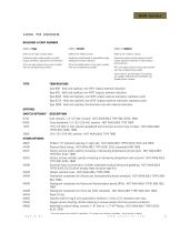
how to order Building a part number Select a Type Refer to the “Type” section below. Refer to the “Model Charts.” Refer to the “Options” section. Determine type number based on switch output, enclosure, adjustment and reference. Determine model based on adjustable range, deadband and proof pressure. Fill in the type portion of your part number with the corresponding number. Fill in the model portion of your part number with the corresponding number. Determine option number based on switch output, optional materials or other product enhancements. Fill in the option portion of your part...
Open the catalog to page 5
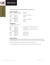
options for temperature models UNION CONNECTORS** Option Replacement Number Description Brass W027 SD6213-27 1⁄2” NPT w/ 3⁄4” bushing W045 SD6213-45 3⁄4” NPT W051 SD6213-51 1⁄2” NPT 304 Stainless Steel W028 SD6213-28 1⁄2” NPT w/ 3⁄4” bushing W046 SD6213-46 3⁄4” NPT W050 SD6213-50 1⁄2” NPT THERMOWELLS** For all bulb & capillary switches Brass W075 SD6225-75 1⁄2” NPT with 3⁄4” NPT adapter bushing, 4” BT W191 SD6225-191 1⁄2” NPT, 4” BT W118 SD6225-118 1⁄2” NPT with 3⁄4” NPT adapter bushing, 7” BT W192 SD6225-192 1⁄2” NPT, 7” BT 316 Stainless Steel W076 SD6225-76 3⁄4” NPT, 4.5” BT W193...
Open the catalog to page 6
dimensional drawings (Dimensional drawings for all models may be found at www.ueonline.com) 800 Series External Set Point Adjustment & Temperature Indication Types 800 & T800 SET POINT INDICATING POINTER (SWITCH #2) RED SET POINT INDICATING POINTER (SWITCH #1) GREEN SET POINT ADJUSTMENT KNOBS TEMPERATURE INDICATING POINTER. (BLACK) †Type T800 has no set point indicating pointer.
Open the catalog to page 7
RECOMMENDED PRACTICES AND WARNINGS United Electric Controls Company recommends careful consideration of the following factors when specifying and installing UE pressure and temperature units. Before installing a unit, the Installation and Maintenance instructions provided with unit must be read and understood. • To avoid damaging unit, proof pressure and maximum temperature limits stated in literature and on nameplates must never be exceeded, even by surges in the system. Operation of the unit up to maximum pressure or temperature is acceptable on a limited basis (e.g., start-up, testing)...
Open the catalog to page 8All United Electric Controls catalogs and technical brochures
-
55 Series
8 Pages
-
J6 Series
8 Pages
-
24 Series
8 Pages
-
J21K Series
8 Pages
-
400 series
16 Pages
-
117 Series
12 Pages
-
Sensor Box
8 Pages
-
120 Series
28 Pages
-
Wireless Solutions
4 Pages
-
100 Series
15 Pages
-
10 Series
8 Pages
-
One Series
16 Pages
-
12 Series
16 Pages
-
AST Catalog
12 Pages
-
PSI Catalog
8 Pages
-
54 Series
12 Pages
-
J40 Series
8 Pages
Archived catalogs
-
UE Catalog SFC-14
16 Pages
-
UE Catalog SFC-11
16 Pages
-
TX200/TX200H Series
12 Pages
-
ue short form catalog
16 Pages
-
pressure transmitter
12 Pages


