- Catalogs
- United Electric Controls
- 54 Series
54 Series
1 /12Pages

54 Series
1 /12Pages
Catalog excerpts

PRESSURE, VACUUM AND TEMPERATURE features • Compact Size • Wide Selection of Adjustable Ranges: Pressure: 30” Hg Vac to 6000 psi (-1 to 413,7 bar) Temperature: -130 to 650°F (-90 to 343.3°C) • Choice of One or Two Switch Outputs • Adjustable or Narrow Deadband Options • Reference Dial or Hex Screw Set Point Adjustment LEADERS IN SAFETY, ALARM & SHUTDOWN
Open the catalog to page 1
The 54 Series offers the OEM a combination of reliable performance and low cost. Available in pressure and temperature versions, with single or dual SPDT outputs and enclosed or open frame (skeleton) construction, the 54 Series family provides design versatility. • Compact size The 54 has been field-proven in a wide variety of OEM applications, including medical, laboratory, fire protection and heating equipment. • Choice of one or two switch outputs • Reference dial or hex screw-type setting • Optional 1/2” NPT (male) by 1/8” NPT (female) polysulfone® pressure connection • Optional external...
Open the catalog to page 2
specifications Storage temperature Ambient temperature limits Pressure Models Temperature Models Shock Vibration ENCLOSURE classification Set point REPEATABILITY Pressure Models Temperature Models Switch output Electrical rating Enclosure MATERIAL Weight Electrical connection Pressure connection Temperature AssemblY Temperature Fill Temperature deadband Models 126-164, 610-614: -40 to 160°F (-40 to 71°C); Models 22-28; 16008, 16009: 0 to 160°F (-18 to 71°C) -40 to 160°F (-40 to 71°C). Set point typically shifts less than 1% of range for a 50°F (28°C) ambient temperature change. Set point repeats...
Open the catalog to page 3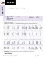
PRESSURE MODEL CHART Model Adjustable Set Point Deadband Over Proof Range Range Pressure* Pressure** High end of range on rise psi (unless noted) bar (unless noted) psi (unless noted) bar (unless noted) psi bar psi bar Buna N diaphragm and O-Ring with 1/4" NPT (male) aluminum pressure connection; limited to process temperature below 200°F 25 10 to 100 0,7 to 6,9 1 to 2.5 68,9 to 172,4 mbar f 100 f 6,9 I above I above 27 30 to 300 2,1 to 20,7 1.3 to 4 89,6 to 275,8 mbar < above < above 1 set point 1 set point 28 50to500 3,4to34,5 1.5to6 103,4 to 344,7 mbar L set point L set point LlVlax600 L Max...
Open the catalog to page 4
temperature model chart Adjustable Set Point Range Scale*** Division Stem Size E54S, F54S, Stainless steel bulb and capillary D21BS D22BS D23BS ‡ Not available Type F54 *** Applies to Types B54, B54S, E54, E54S only
Open the catalog to page 5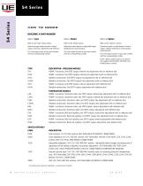
BUILDING A PART NUMBER Refer to the "Type" section below. Determine type number based on switch output, enclosure, adjustment and reference. Fill in the type portion of your part number with the corresponding number. Refer to the "Model Charts." Determine model based on adjustable range, deadband and proof pressure. Fill in the model portion of your part number with the corresponding number. Refer to the "Options" section. Determine option number based on switch output, optional materials or other product Fill in the option portion of your part number with the corresponding number. Leave "option"...
Open the catalog to page 6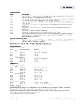
54 Series GENERAL OPTIONS CODE M201 DESCRIPTION Factory set one switch; specify increasing or decreasing pressure or temperature and set point. NOT AVAILABLE ON TYPES J54A, J54AS, C54A, C54AS AND MODELS 16008-16009. M202 Factory set two switches; specify increasing or decreasing pressure or temperature and set point. NOT AVAILABLE ON TYPES J54, J54S, H54, H54S, B54, B54S, C54, C54S, E54, E54S, F54, F54S M270 Calibrated dial in Celsius. NOT AVAILABLE ON PRESSURE VERSIONS AND TYPES B54, B54S, C54, C54S, C54A, C54AS, F54, F54S M277 Range indicated on nameplate in kPa or MPa. NOT AVAILABLE ON TEMPERATURE...
Open the catalog to page 7
dimensional drawings Pressure Models Type H54, J54 and J54A Models 22 - 28, 16009 #8-32 TERMINAL SCREW 3 PLACES CL. FOR #6 SCREW 2 HOLES (WALL MT'G.) WRENCH FLATS
Open the catalog to page 8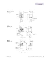
WALL MOUNTING WALL MOUNTING. VENT HOLE LOCATION. WRENCH FLATS UNITED ELECTRIC CONTROLS
Open the catalog to page 9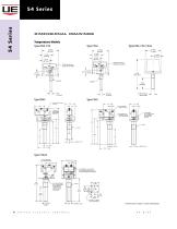
DIMENSIONAL DRAWINGS Temperature Models Electrical Connection Electrical Connection MAIN ADJUSTMENT: SETTING (BOTH LOWER TEMPERATURE SETTING - WRENCH FLATS All dimensions stated in inches (millimeters)
Open the catalog to page 10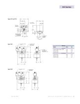
WALL MOUNTING TEMPERATURE SETTING UNITED ELECTRIC CONTROLS 11
Open the catalog to page 11
RECOMMENDED PRACTICES AND WARNINGS United Electric Controls Company recommends careful consideration of the following factors when specifying and installing UE pressure and temperature units. Before installing a unit, the Installation and Maintenance instructions provided with unit must be read and understood. • To avoid damaging unit, proof pressure and maximum temperature limits stated in literature and on nameplates must never be exceeded, even by surges in the system. Operation of the unit up to maximum pressure or temperature is acceptable on a limited basis (e.g., start-up, testing) but...
Open the catalog to page 12All United Electric Controls catalogs and technical brochures
 55 Series
8 Pages
 J6 Series
8 Pages
 24 Series
8 Pages
 J21K Series
8 Pages
 800 series
8 Pages
 400 series
16 Pages
 117 Series
12 Pages
 Sensor Box
8 Pages
 120 Series
28 Pages
 Wireless Solutions
4 Pages
 100 Series
15 Pages
 10 Series
8 Pages
 One Series
16 Pages
 12 Series
16 Pages
 AST Catalog
12 Pages
 PSI Catalog
8 Pages
 J40 Series
8 Pages

Archived catalogs
 UE Catalog SFC-14
16 Pages
 pressure transmitter
12 Pages
 ue short form catalog
16 Pages
 TX200/TX200H Series
12 Pages
 UE Catalog SFC-11
16 Pages


- ERLO temperature sensor
- ERLO resistance temperature sensor
- ERLO pressure transmitter
- ERLO analog pressure transmitter
- ERLO pressure switch
- ERLO gas detector
- ERLO membrane pressure transmitter
- Thermocouple temperature transducer
- Mechanical pressure switch
- ERLO digital pressure transmitter
- ERLO waterproof pressure switch
- ERLO threaded pressure transmitter
- ERLO monitoring detector
- ERLO process pressure transmitter
- ERLO infrared detector
- Process temperature sensor
- ERLO adjustable pressure switch
- Liquid pressure switch
- ERLO explosion-proof pressure transmitter
- ERLO gas pressure switch