
Catalog excerpts

DIFFERENTIAL PRESSURE • Match process requirements with brass or polysulfone (FDA compliant) pressure connections • Space-saving compact size • Watertight with optional conduit fitting • Simplified terminal block wiring • Optional red status light provides switch indication • Adjustable Ranges: Differential Pressure: 1 to 45 psid (68,9 mbar to 3,1 bar) LEADERS IN SAFETY, ALARM & SHUTDOWN
Open the catalog to page 1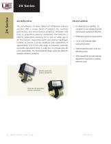
The cost-effective 24 Series Delta-Pro™ differential pressure switches offer a unique blend of compact size, excellent performance, and environmental protection. Available with brass or polysulfone pressure connections, the Delta-Pro is ideal for applications involving hot or cool air, water, gas or oil. The precision snap-acting switch and sensitive diaphragms combine to provide a narrow deadband and repeatability of approximately ±1% of full scale range. A convenient, externally accessible adjustment screw is multi-turn to provide easy set point adjustability. force-balanced design gives...
Open the catalog to page 2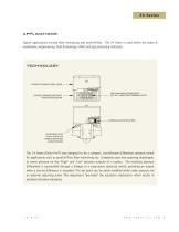
applications Typical applications include filter monitoring and proof-of-flow. The 24 Series is used within the water & wastewater, bioprocessing, food & beverage, HVAC and gas processing industries. GASKETED STAINLESS STEEL COVER STRONG, CORROSIVE RESISTANT POLYESTER ENCLOSURE PRECISION SNAP-ACTING SWITCH N.O., N.C., COM SCREW TERMINALS (SPDT) EXTERNAL ADJUSTING SCREW CLEARANCE HOLES FOR #6 SCREW FOR SURFACE MOUNTING IN ANY POSITION The 24 Series (Delta Pro™) was designed to be a compact, cost-effective differential pressure switch for applications such as proof-of-flow, filter monitoring,...
Open the catalog to page 3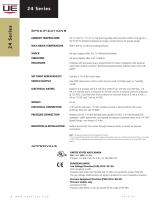
specifications AMBIENT TEMPERATURE 30° to 160°F (-1° to 71°C). Set point typically shifts less than ±0.6% of range for a 50°F (28°C) ambient temperature change; consult factory for special ratings Set point repeats after 15G, 10 millisecond duration Set point repeats after 2.5G, 5-500 Hz Complies with enclosure type 4 requirements for indoor installation with optional water tight conduit connector. Reinforced polyester body, stainless steel cover with gasket. Typically ± 1% of full scale range. SWITCH OUTPUT One SPDT snap-action switch; switch may be wired "normally open" or "normally...
Open the catalog to page 4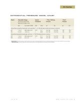
differential pressure model chart Model Adjustable Range Low end of range of fall High end of range on rise psid Typical Deadband *Proof Pressure Polyurethane (polyether) diaphragm and polysulfone® 1/4” NPS (female) (mechanical) pressure connection 011 012 Polyurethane (polyether) diaphragm and brass 1/4” NPT (female) pressure connection 013 014 *Proof Pressure: The maximum pressure to which a pressure sensor may be occasionally subjected, which causes no permanent damage. The unit may require calibration (e.g. start-up, testing). **Working Pressure: The pressure range within which two...
Open the catalog to page 5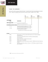
how to order Build a part number by selecting a model and options. Choose the Sensor Type and the Range from the Model Chart. If options are required, add the code from the option list below. Example: 24-013 * M900. SERIES DESIGNATION Designation for 24 Series product line DIFFERENTIAL PRESSURE MODELS * Polyurethane (polyether) diaphragm and 1/4” NPS (female) (mechanical) polysulfone pressure connection Polyurethane (polyether) diaphragm and 1/4” NPT (female) brass pressure connection *(See Model Chart for Differential Pressure Ranges) Red status light, 115 VAC only. Specify whether light...
Open the catalog to page 6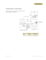
dimensional drawings Dimensional drawings for all models may be found at www.ueonline.com All dimensions stated in inches (millimeters) Pressure Connection
Open the catalog to page 7
RECOMMENDED PRACTICES AND WARNINGS United Electric Controls Company recommends careful consideration of the following factors when specifying and installing UE pressure and temperature units. Before installing a unit, the Installation and Maintenance instructions provided with unit must be read and understood. • To avoid damaging unit, proof pressure and maximum temperature limits stated in literature and on nameplates must never be exceeded, even by surges in the system. Operation of the unit up to maximum pressure or temperature is acceptable on a limited basis (e.g., start-up, testing)...
Open the catalog to page 8All United Electric Controls catalogs and technical brochures
-
55 Series
8 Pages
-
J6 Series
8 Pages
-
J21K Series
8 Pages
-
800 series
8 Pages
-
400 series
16 Pages
-
117 Series
12 Pages
-
Sensor Box
8 Pages
-
120 Series
28 Pages
-
Wireless Solutions
4 Pages
-
100 Series
15 Pages
-
10 Series
8 Pages
-
One Series
16 Pages
-
12 Series
16 Pages
-
AST Catalog
12 Pages
-
PSI Catalog
8 Pages
-
54 Series
12 Pages
-
J40 Series
8 Pages
Archived catalogs
-
UE Catalog SFC-14
16 Pages
-
UE Catalog SFC-11
16 Pages
-
TX200/TX200H Series
12 Pages
-
ue short form catalog
16 Pages
-
pressure transmitter
12 Pages


