- Catalogs
- UniPi.technology
- Unipi Neuron
Unipi Neuron
1 /28Pages
Unipi Neuron
1 /28Pages
Catalog excerpts

Product line of programmable controllers and extension modules Unipi Neuron
Open the catalog to page 1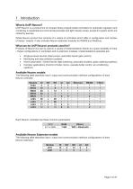
UniPi Neuron is a product line of compact freely programmable controllers for automatic regulation and monitoring in residential and commercial premises and light industry areas, except for system which are critical for security. Whole Neuron product line consists of a variety of controllers which differ in configuration and number of inputs / outputs. It also includes Neuron extension modules for RS485 bus (Modbus). Products of Neuron line can be used in a variety of implementations thanks to a great variability of Input / Output configurations in controllers and in extension modules. Implementations...
Open the catalog to page 4
Devices of Neuron product line have CE marking and ES Declaration of Conformity. They are compliant with CSN EN 6095-1 ed. 2, CSN EN 61000-6-3 ed. 2, CSN EN 55014-1 ed. 3, CSN EN 55022 ed. 3 and with EMC standards. Products are also compliant with government orders and EU directives including all amendments: • GD no. 17/2003 Coll. as amended, 2006/95/EC - including amendments • GD no. 616/2006 Coll. as amended, 2004/108/ES - including amendments Device is to be distributed as a development board.
Open the catalog to page 5
2 Installation and connection Basic instructions Always follow these instructions during the installation: • • • • • • Make sure you meet the actual standards and rules and all regional and state regulations. Always turn off the power supply before any manipulation (mounting / demounting). Use a wire with appropriate wire gauge. Do not exceed screw torque of removable screw connectors. Follow installation and operating conditions. Keep the cabling as short as possible. If longer cables are necessary, you should use shielded versions. You should always route your cables in pairs: i.e. one neutral...
Open the catalog to page 6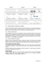
2.2 Control units and extension modules Control units compared to extension modules feature CPU and memory for custom program settings on OS Linux (for more see chapter 3). Extension modules are connected to control units over RS485 with Modbus communication protocol and it is not possible to store custom system within. 2.2.1 Neuron control units The advantage of control units is the possibility to load custom program thanks to the open Linux platform. The other advantage is a high-speed communication within the unit resulting in minimal latency when executing commands. Control units also feature...
Open the catalog to page 7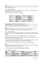
Models, where the communication speed and parity cannot be set by hardware, are preconfigured to use 19 200 bps without parity. The integrated DIP switch is used to configure communication of the device. Purpose of each switch is always described atop the box above the DIP switch. Purpose of each switch also describes the following table:
Open the catalog to page 8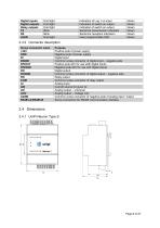
2.4.1 UniPi Neuron TypeS
Open the catalog to page 9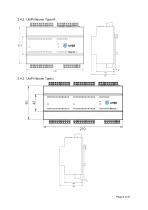
2.4.3 UniPi Neuron Type L
Open the catalog to page 10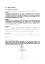
2.5 Device mounting 2.5.1 Mounting / demounting All products of the Neuron product line are designed for mounting onto 35 mm DIN EN 50022. Mounting Mounting of product onto the rail should be done as follows – attach the product onto the rail, first by the side of DIN rail holder which has the metal spring. Then by pulling against, you squeeze the spring and pull the other side of the holder over the rail edge. If no DIN rail holder is attached to the Neuron product it is necessary to attach it first with provided screws. When attaching the DIN rail holder, the metal spring must be positioned...
Open the catalog to page 11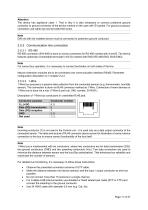
The device has appliance class 1. That is why it is also necessary to connect protective ground conductor to ground connector of the device marked on the case with © symbol. For ground conductor connection use cable eye and provided M4 screw. DIN rail with the installed device must be connected to protective ground conductor. RS-485 connection (EIA-485) is done on screw connectors for RS-485 marked with A and B. The device features optionally connectable terminator (100 Q) marked with END (RS-485-END, BUS-END). For correct bus operation, it is necessary to connect terminator on both sides of...
Open the catalog to page 12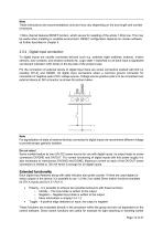
Note These instructions are recommendations only and may vary depending on the bus length and number of sensors. 1-Wire channel features RESET function, which serves for resetting of the whole 1-Wire bus. This may be useful when installing in unstable environment. RESET configuration depends on chosen software as further described in chapter 3. 2.5.4 Digital input connection To digital inputs are usually connected devices such e.g. switches (light switches, buttons), motion sensors, door contacts, and window contacts etc. Logic state 1 (switched on) of each input is signalized via relevant indication...
Open the catalog to page 13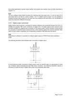
time-critical applications (typical output reaction time equals input reaction time as further described in chapter 4.1). Note You can configure Direct Switch functions for matching input and output only, i.e. only for input DiY.X and output DoY.X (or RoY.X), where number Y (if Y is stated) must be equal. It is not possible to configure function Direct Switch for one input and more outputs at the same time or for combination of input and output from different I/O Groups. 2.5.5 Digital output connection Digital outputs (semiconductor, connected as opened collectors) are accessible through DoX...
Open the catalog to page 14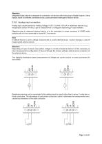
Attention Integrated flyback diode is designed for connection od devices within the group of digital outputs. Using flyback diode for different connections may cause permanent damage to Neuron device. 2.5.6 Analog input connection Analog input usually serves for reading Voltage 0-10 V, Current 0-20 mA or resistance sensors (e.g. temperature sensor Pt1000). Type of measurement is configured depending on used software. Negative pole of measured external device is to be connected to screw connector of AGND while positive pole is to be connected to screw AIY.X connector. Note In default Neuron is...
Open the catalog to page 15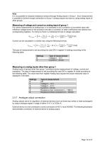
Note It is not possible to measure resistance sensors through Analog inputs in Group 1. Such measurement is possible to achieve trough connection to Group 1 analog outputs and also by using analog inputs of other groups. Measuring of voltage and current on analog input of group 1 For correct measurement of analog input, it is necessary to do a correction of converted value with reference voltage stored in the processor and also a correction of other coefficients read directly from corresponding registers. For doing so there is a following formula of voltage calculation. ݑȰݑȰݐݐݐݐ1ݑpݑpݑpݑpݑpݑpݑpݑ...
Open the catalog to page 16All UniPi.technology catalogs and technical brochures
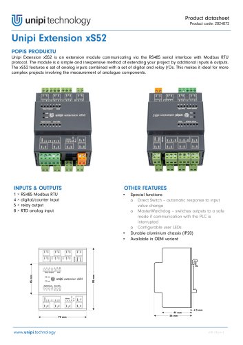 Unipi Extension xS52
3 Pages
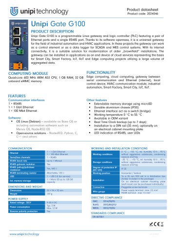 Unipi Gate G100
1 Page
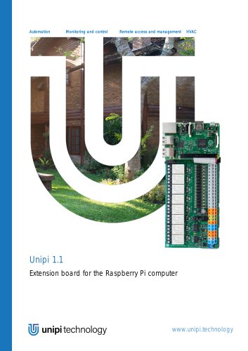 Unipi 1.1
14 Pages
- Automation software solution
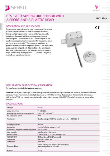
- Resistance temperature sensor
- Cloud-based software
- Interface software
- Waterproof temperature sensor
- Industrial gateway
- Single-board computer
- Ethernet gateway
- Humidity and temperature probe
- Programmable logic controller
- Programming software
- Development software
- Serial gateway
- Relative humidity and temperature sensor
- DIN rail gateway
- IoT gateway
- RS-485 gateway
- Waterproof humidity and temperature sensor
- IP65 temperature transducer