- Catalogs
- UniPi.technology
- Unipi 1.1
Unipi 1.1
1 /14Pages
Unipi 1.1
1 /14Pages
Catalog excerpts
Remote access and management Unipi 1.1 Extension board for the Raspberry Pi computer
Open the catalog to page 1
m unipi technology User guide and technical documentation
Open the catalog to page 2
User guide and technical documentation m unipi technology1 Introduction Unipi 1 is an add-on board for the Raspberry Pi (RPi). It features many components such as 12(+2) digital inputs with LED signalization, two 0-10 V analog inputs, one 0-10 V analog output, 8 changeover relays, single-channel 1wire master controller and a real-time clock module. The two digital inputs I13, I14 and the I2C_0 bus are designed for connection via the P5 RPi B header (only), which is no longer available on newer Raspberry Pis (B+ and newer) models. We provide open-source API EVOK and Modbus TCP server Unipi One...
Open the catalog to page 3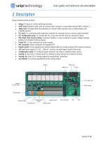
User guide and technical documentation 2 Description Major building blocks of Unipi: • Relays: 8 relays to control switching elements • UART port: Standard serial port to connect serial console or many other devices (NFC readers, ..) • 1Wire port: Provides 1Wire bus interface to connect 1Wire devices such as temperature and humidity sensors • I2C port: For connecting other extension modules for example relay or analog output modules • I2C configuration pins: To connect the I2C_0 bus from the RPi (only for advanced users) • RTC (Real Time Clock) module: Provides real-time in case of internet or...
Open the catalog to page 4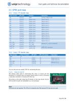
User guide and technical documentation m unipi technology2.1 GPIO port map2.1.1 Unipi 1 P1 header map RPi BCM Function Unipi function You can also use any unused GPIO for connecting the pins. The default cable used to interconnect the Unipi 1.1 board and the Raspberry Pi computer does not support digital inputs 13 and 14. Meaning a separate connection is necessary for their use. The picture on the right, shows the P5 header on the Unipi board. Pins for IN13 and IN14 inputs are highlighted by a red rectangle. GND pins are not required. The 3V3 pin is required only if the second I2C bus pins are...
Open the catalog to page 5
User guide and technical documentation The main Unipi power connector is standard 2.1 mm inner diameter, 5.5 mm outer diameter with +5 V DC connected on the center. There are two options of powering the Unipi board and Raspberry Pi: • A single power source (RPi and Unipi are powered from the same power source) • 5 V DC, 2.4 A through the Unipi power connector (750 mA for Unipi + RPi requirements) • Please note that Unipi board can only provide 1.5 A to the RPi • Raspberry Pi (USB) power connector is not used • For Raspberry Pi 4 it is advisable to increase the (no-load) voltage of the power supply...
Open the catalog to page 6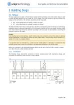
User guide and technical documentation 3 Building blogs 3.1 Relays The relay outputs are located on the terminals marked with the schematic mark of the switch, they are used to switch two-state devices and can switch AC or DC voltage. The COM terminal is typically common, the voltage is then at the NO or NC terminal, depending on the relay state. • • NO - in the default state (no voltage), contacts are open NC - in the default state (no voltage), contacts are closed The state (On/Off) of each relay is indicated by a LED with a corresponding label. Overload and overvoltage protection should be...
Open the catalog to page 7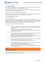
User guide and technical documentation 3.2 Digital Inputs These inputs can be triggered by 7 24 V DC voltage with a minimum pulse length of debounce time. For the easy visual reading of their states, all inputs are equipped with LED. When using the GPIOs make sure to set a software pull-up resistor on each GPIO to make it work properly otherwise state of the GPIO cannot be read properly. 3.2.1 5 12 V Step-up (internal 12 V power supply) All digital inputs are primarily set to be driven by the internal 12 V power supply. The 12 V line is wired out via the orange connector marked as 12 V. Do not...
Open the catalog to page 8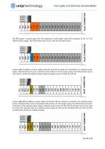
User guide and technical documentation The JP2 jumper is moved away from the Raspberry Pi with digital inputs still connected to the 12 V DC internal power supply. The P02 terminal now acts as GND for the entire board: Jumpers JP2 and JP3 are moved, digital inputs I01 and I02 are ready for connection of an external power supply. Terminals I03 to I14 are connected to the internal 12 V DC power supply. The P02 terminal can be now used to connect the external power supply's negative pole for inputs I01 and I02: Jumpers JP2, JP3 and JP4 are moved, digital inputs I01 to I04 are ready for connection...
Open the catalog to page 9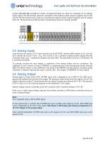
User guide and technical documentation Jumpers JP2, JP3, JP4 and JP5 are moved, all digital terminals are ready for connection of an external power supply. The P02 terminal serves for connection of the external power supply's negative pole for I01 and I02. The P01 terminal now serves for connecting the external power supply's negative pole for outputs I03 to I14. Terminals P01 and P02 and their corresponding inputs are mutually isolated: 3.3 Analog Inputs Unipi features two analog 0 10 V input channels (via the MCP3422, address 0x68) marked as AI1 and AI2. Each channel has its own + and (e.g.,...
Open the catalog to page 10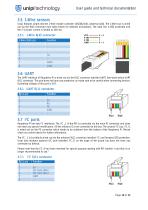
User guide and technical documentation m unipi technology3.5 1-Wire sensors Unipi features single-channel 1-Wire master controller (DS2482-100, address 0x18). The 1-Wire bus is wired out via the RJ45 connector (see table below for detailed description). The data line is ESD protected and the 5 V power current is limited to 200 mA. 3.6 UART The UART interface of Raspberry Pi is wired out via the RJ11 connector labelled UART. See table below UART RJ11 connector. This port does not have any protection, so make sure to be careful when connecting devices. Operating voltage of this port is 3V3. Raspberry...
Open the catalog to page 11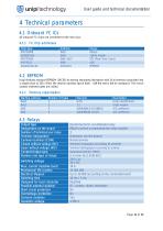
User guide and technical documentation m unipi technology4 Technical parameters4.1 Onboard I2C ICs All onboard I2C chips are connected to the main bus.
Open the catalog to page 12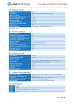
User guide and technical documentation m unipi technology 4.4 Digital Inputs
Open the catalog to page 13
User guide and technical documentation m unipi technologyRevision Date Compliance information Unipi 1.1 complies with the requirements of EMC, LVD, and RoHS regulations relevant for European Union states. WEEE Directive Statement for the European Union Unipi 1.1 cannot be disposed of as household waste. Different rules for handling electric waste may apply in otherjurisdictions.
Open the catalog to page 14All UniPi.technology catalogs and technical brochures
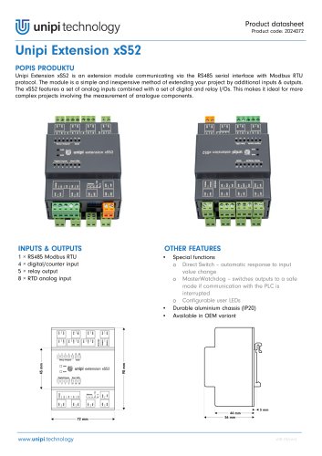 Unipi Extension xS52
3 Pages
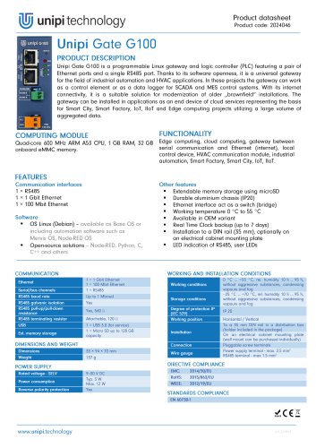 Unipi Gate G100
1 Page
 Unipi Neuron
28 Pages
- Temperature probe
- Automation software solution
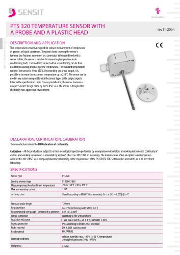
- Resistance temperature sensor
- Cloud-based software
- Interface software
- Waterproof temperature sensor
- Industrial gateway
- Single-board computer
- Ethernet gateway
- Humidity and temperature probe
- Programmable logic controller
- Programming software
- Development software
- Serial gateway
- Relative humidity and temperature sensor
- DIN rail gateway
- IoT gateway
- RS-485 gateway
- Waterproof humidity and temperature sensor
- IP65 temperature transducer