
Catalog excerpts

MAINTENANCE AND ASSEMBLY INSTRUCTIONS PNCE ELECTRIC CYLINDERS
Open the catalog to page 1
INDEX General information Symbols used Recommended tightening torques for screws General safety instructions Safe operation Modi cation of the electric cylinder Operating conditions Product description Standard version IP65 protection class with high corrosion resistance (IP65CR) For applications in the food industry (FI) Identi cation label and additional or replacement parts of the electric cylinder Handling the electric cylinder Storing the electric cylinder Accessories - overview Permissible loads Magnetic eld sensor - reed switch Motor adapter with coupling Motor side drive with timing...
Open the catalog to page 2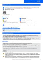
ELECTRIC CYLINDERS WITH A BALLSCREW DRIVE GENERAL INFORMATION It is important to read this instruction manual before handling the product. Otherwise the electric cylinder might get damaged. Some detailed information, which is not presented in this document, can be found in our catalogue UNIMOTION Electric cylinder PNCE. Link to the catalogue Unimotion Electric cylinder PNCE Used symbols Remark, note Tightening torque For more information see the catalogue Danger! Risk of coming into contact with power conducting parts! Cut o the power supply! Use di erent tightening torques as are presented...
Open the catalog to page 3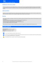
MAINTENANCE- AND ASSEMBLY INSTRUCTIONS Modi cation of the electric cylinder The electric cylinder must not be modi ed without our written consent. Any such unauthorized modi cation will make void our liability in respect of the unit (cylinder). The operating company may only carry out the maintenance and repair work detailed in this Instruction manual. Labels and notices All notices and labels attached to the electric cylinder must be fully visible and must not be removed. They must ensure compliance with all the instructions contained on them. Damaged or illegible notices and labels must...
Open the catalog to page 4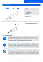
MAINTENANCE- AND ASSEMBLY INSTRUCTIONS PRODUCT DESCRIPTION Standard version (S)* 4 1 – Front cap 2 – Drive cap 3 – Smooth cylinder pro le 4 – Hex nut 5 – Piston rod (stainless steel) with an anti-rotation device 6 – Piston rod seal 7 – Pressure compensation 8 – Lubrication nipple * IP40 protection class Figure 1: Structural design of the standard version of the PNCE. 9 – Connection for pressure compensation 9 Figure 2: Structural design of the IP65 version of the PNCE. IP65 protection class (IP65) The appropriate sealing of the external parts ensures the electric cylinder the IP65...
Open the catalog to page 5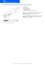
MAINTENANCE- AND ASSEMBLY INSTRUCTIONS Identi cation label and additional or replacement parts of the electric cylinder 1 - ID number 2 - Serial number 3 - No load torque [Nm] 4 - Axial backlash [mm] 5 - Type of electric cylinder (ordering code) In case of ordering additional or replacement parts for the electric cylinder all data must be given from the identi cation label. The label must be fully visible and must ensure compliance with all the instructions it contains. Damaged or illegible labels must be replaced. Figure 3: Identi cation label of the electric cylinder. In order to improve...
Open the catalog to page 6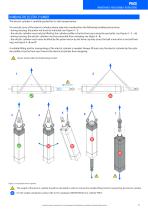
MAINTENANCE- AND ASSEMBLY INSTRUCTIONS HANDLING THE ELECTRIC CYLINDER The electric cylinder is carefully packed for its safe transportation. To correctly carry of the electric cylinder, please take into consideration the following handling instructions: - during carrying, the piston rod must be retracted, see Figure 4 - 1, - the electric cylinder must only be lifted by the cylinder pro le or by the front cap (using the eye bolts), see Figure 4 - 1 6, - during carrying, the electric cylinder must be prevented from swinging, see Figure 4 - 4, - the electric cylinder must never be lifted by...
Open the catalog to page 7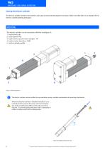
MAINTENANCE- AND ASSEMBLY INSTRUCTIONS Storing the electric cylinder The electric cylinder needs to be stored in a dry place and protected against corrosion. Make sure that there is no danger of the electric cylinder getting damaged. MOUNTING The electric cylinder can be mounted as follows (see gure 5): 1 - by the front cap 2 - by the piston rod 3 - by the drive cap and motor adapter - VK 4 - by the motor side drive - MSD 5 - by the cylinder pro le Figure 5: Mounting options. The electric cylinder can be installed in any orientation using a suitable combination of mounting attachments. When...
Open the catalog to page 8
MAINTENANCE- AND ASSEMBLY INSTRUCTIONS Accessories - overview Figure 7: Accessories - overview Page Piston rod accessories Mounting attachment accessories Guiding unit Table 2: Accessories - overview For information about materials, dimensions and the maximum permissible loads of the accessories, see the catalogue UNIMOTION Electric cylinder PNCE. Mounting accessories are not pre-assembled to the electrical cylinder in the factory before shipment. In order to improve the products in this catalogue the speci cations are subject to change without notice.
Open the catalog to page 9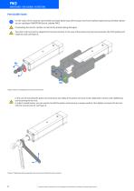
MAINTENANCE- AND ASSEMBLY INSTRUCTIONS Permissible loads For the values of the maximum permissible axial load, lateral load, drive torque, travel and rotational speed and acceleration please see our catalogue UNIMOTION Electric cylinder PNCE. Overloading the electric cylinder can lead to the product being damaged. The piston rod must not be subjected to torsional moment. In the case of the presence of any torsional loads, the GUH guiding unit might be used, see Figure 8. Mx Figure 8: Piston rod subjected to torsional moment Mx. In the case of mounting the piston rod accessories (see Table...
Open the catalog to page 10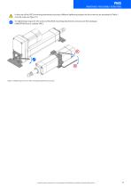
MAINTENANCE- AND ASSEMBLY INSTRUCTIONS In the case of the ZKCE mounting attachment accessory, di erent tightening torques for the screws as are presented in Table 1, must be used, see Figure 10. For tightening torques for the screws of the ZKCE mounting attachment accessory see the catalogue UNIMOTION Electric cylinder PNCE. Figure 10: Tightening the screws of the mounting attachment accessories. In order to improve the products in this catalogue the speci cations are subject to change without notice.
Open the catalog to page 11
MAINTENANCE- AND ASSEMBLY INSTRUCTIONS MAGNETIC FIELD SENSOR - REED SWITCH STEP 1 and 2 STEP 1: The magnetic eld sensor must rst be mounted on the sensor holder 1. Tighten the screw of the magnetic eld sensor - REED switch with a tightening torque of max. 0,6 Nm. STEP 2: Place the sensor holder 1 together with the magnetic eld sensor on the electric cylinder pro le, see Figure 12. For INFO about slots and dimensions of the sensor holder 1 see catalogue UNIMOTION Electric cylinder PNCE. The sensor holder can be placed on both sides of the electric cylinder pro le. Magnetic field sensor...
Open the catalog to page 12All UNIMOTION catalogs and technical brochures
-
 Product overview
16 Pages
-
 Company overview
8 Pages
-
 Company Unimotion
2 Pages
-
 CTL Linear units
32 Pages
-
 Mini linear units
81 Pages
-
 Mini electric cylinders
100 Pages
-
 LMCA Linear motors
36 Pages
-
 UNIMOTION stepper system
32 Pages
-
 Electric cylinder
40 Pages
-
 Linear Units
140 Pages


