
Catalog excerpts

MAINTENANCE AND ASSEMBLY INSTRUCTIONS MTV SERIES
Open the catalog to page 1
The specifications in order to improve the products in this catalogue are subject to change without notice.
Open the catalog to page 2
CONTENTS GENERAL INFORMATION Used symbols Tightening torques General safety instructions Safe operation Modification of the linear unit Labels and notices Warranty Handling the linear unit Product description Overview MAINTENANCE _ Lubrication of the ball nut and the carriage Lubrication of the cover strip _ Lubricant _ Lubricant quantities and intervals _ Normal operating conditions _ REPLACEMENT OF ASSEMBLIES Removing the cover plate _ Replacing the protection strip _ Replacing the protection strip MTV 40 Replacing the floating bearing _ Removing the spindle and spindle nut Replacing the...
Open the catalog to page 3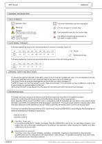
GENERAL INFORMATION USED SYMBOLS Remark, note Linear Units Linear Units Linear Units Linear Units Linear Units For more information see the catalogue Do not use glue in current step Use dedicated tools for the current step Risk of coming into contact with power conducting parts! Cut off power supply! Keep Linear Unit clean! Cover it, if necessary! Use different tightening torque than in the table on page 1.005.0 TIGHTENING TORQUES Following tightening torques are recommended for screws of strength class 8.8 8.8 Screw Tightening torque Following tightening torques are recommended for screws...
Open the catalog to page 4
MODIFICATION OF LINEAR UNIT The linear unit must not be modified without our written consent. Any such unauthorised modification will void our liability in respect of the unit. The operating company may only carry out the maintenance and repair work detailed in this Instruction manual. LABELS AND NOTICES All notices and labels attached to the linear unit must be fully visible and must not be removed. They must ensure compliance with all the instructions contained on them. Damaged or illegible notices and labels must be replaced. WARRANTY The warranty conditions are laid down in the terms...
Open the catalog to page 5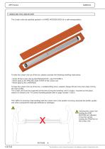
HANDLING THE LINEAR UNIT The Linear units are carefully packed in a HARD WOODEN BOX for a safe transportation. To take the Linear Unit out of the box, please consider the following handling instructions: - Never lift the Linear Unit by the END BLOCKS - see PICTURE A - Never grab by the PROTECTION STRIP of the Linear Unit - Never grab by the CARRIAGE To take the Linear Unit out of the box, a suitable lifting tool is needed. Always lift and carry the Linear Unit by the main profile. The Linear Unit must be supported all the time during the handling until it is fixed - mounted on the place,...
Open the catalog to page 6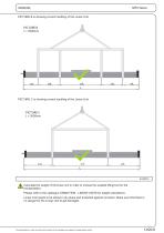
MANUAL PICTURE B is showing correct handling of the Linear Unit. PICTURE C is showing correct handling of the Linear Unit. Calculate the weight of the linear unit in order to choose the suitable lifting tool for the transportation. Please refer to the catalogue UNIMOTION - LINEAR UNITS for weight calculations. Linear Unit needs to be stored in dry place and protected against corrosion. Make sure that there is no danger for the Linear Unit to get damaged. The specifications in order to improve the products in this catalogue are subject to change without notice.
Open the catalog to page 7
PRODUCT DESCRIPTION Drive block with floating bearing Corrosion-resistant protection strip Ball screw tolerance ISO7 (ISO5 available on request) Carriage; with built in Magnets Aluminium profile-Hard anodized Integrated Linear Ball Guideway Central lubrication port; both sides End block with fixed bearing The specifications in order to improve the products in this catalogue are subject to change without notice.
Open the catalog to page 8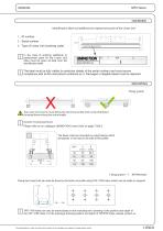
OVERVIEW Identification label and additional or replacement parts of the Linear Unit 1 - ID number 2 - Serial number 3 - Type of Linear Unit (ordering code) In the case of ordering additional or replacement parts for the Linear Unit there must be given all data from the identification label. The label must be fully visible (in particular details of the serial number) and must ensure compliance with all the instructions contained on it. Damaged or illegible labels must be replaced. MOUNTING Fixing system The Linear Unit must be mounted by the aluminium profile with evenly distributed...
Open the catalog to page 9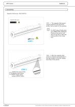
MOUNTING Magnetic field sensor - REED SWITCH Magnetic field sensor STEP 1: The magnetic field sensor must be placed in the slot of the profile, that is made for this purpose. Linear Units Linear Units Linear Units Linear Units Linear Units For INFO about Profile slots see UNIMOTION Catalogue. Placing of the sensor can done on the left or right side of the profile of the Linear Unit. STEP 2: After the magnetic field sensor is inserted and positioned in the right location in the slot, tighten the screw of the sensor. STEP 2 Tighten the screw of the magnetic field sensor REED switch with a...
Open the catalog to page 10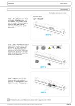
MOUNTING Mechanical and inductive switch Activation block STEP 1: Mount the activation block on the side of the carriage by the thread holes. The activation block can be mounted on the carriage on the left or right side. After the activation block is placed, tighten the screws. STEP 2: Place either the mechanical switch or the inductive switch with brackets in the slots and position them in the desired location. The mechanical or inductive switch with brackets can be placed in the slots either on the left or right side of the profile of the Linear Unit. Mechanical switch with the bracket...
Open the catalog to page 11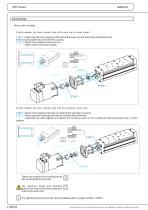
MOUNTING Motor with coupling If motor adapter has inner through hole of the same size its entire length. S T E P 1: Attach one half of the coupling to the shaft of the linear unit and other to the shaft of the motor. Insert coupling spider into one half of the coupling. S T E P 2: Attach motor adapter to the linear unit. S T E P 3: Attach motor to the motor adapter. If motor adapter has inner through hole with the narrowing at one end. S T E P 1: Attach motor adapter to the side on which the through hole is narower. S T E P 2: Attach complete coupling to the axle on the wider side of the...
Open the catalog to page 12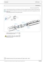
MOUNTING Motor with coupling MTV 40 S T E P 1: Insert centering ring to the linear unit and attach one half of the coupling to the linear unit. Attach connector plate to the motor. S T E P 2: Attach other half of the coupling to the motor and insert coupling spider to either half of the coupling.Attach connector body to the linear unit. S T E P 3: Align coupling halves and join connector plate and body. S TE P 1 S TE P 1 Tighten the screws on the coupling halves with coupling tightening torque. The maximum torque and maximum speed of the motor must never exceed the limits of the Linear...
Open the catalog to page 13All UNIMOTION catalogs and technical brochures
-
 Product overview
16 Pages
-
 Company overview
8 Pages
-
 Company Unimotion
2 Pages
-
 CTL Linear units
32 Pages
-
 Mini linear units
81 Pages
-
 Mini electric cylinders
100 Pages
-
 LMCA Linear motors
36 Pages
-
 UNIMOTION stepper system
32 Pages
-
 Electric cylinder
40 Pages
-
 Linear Units
140 Pages


