- Catalogs
- Uni Klinger Limited
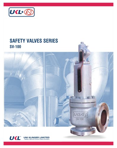
- SV-100 Safety Relief Valve
SV-100 Safety Relief Valve
1 /34Pages
SV-100 Safety Relief Valve
1 /34Pages
Catalog excerpts

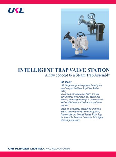
This range of spring loaded conventional Pressure Relief Valves is for installation of any SECTION VIII application and are available from pressure range of 0.3 Bar to 414 Bar and for pressure ratings up to 2500#. Sizes from 1" D 2" to 8" T 12" in different material of construction depending - Safety Valve & Control Valve Division
Open the catalog to page 2
Main Features Flanged, Spring loaded, Direct acting, Full nozzle pressure Media : Gas, Steam and Liquid. Set pressure range : From 0.3barto 414 bar. Temperature range : From -201 o Cto715oC. Materials : Carbon Steel, Alloy Steel, Hastelloy, Monel and other materials upon Options : Bellows, Flushing nozzle, Lifting lever, Test gag, Finned bonnet, Limit switch, Resilient or Hardened seat. Sizes/Pressure Classes Size inlet&outlet: from NPS1 to NPS 8 & from NPS 2 to NPS12 Rating: up to ASME 2500. Special solution ASME 4500 and up Design Codes & Product Standards 521, API 526, API 527, ASME B16.34,...
Open the catalog to page 3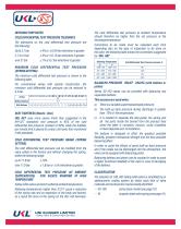
INTRODUCTORY NOTES COLD DIFFERENTIAL TEST PRESSURE TOLERANCE The tolerances on the cold differential test pressure are over 21 bar ±1%orO, 7 bar whichever is greater MINIMUM COLD DIFFERENTIAL TEST PRESSURE (SPRING SETTING) The minimum cold differential test pressure is shown in the following table. For conventional valves with special construction, the minimum cold differential test pressure can be reduced to BALANCED PRESSURE RELIEF VALVES (with bellows or Series SV-100 valves can be provided with balancing and separation bellows. This accessory is used when: a) There is a variable superimposed...
Open the catalog to page 4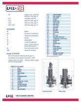
Tungsten steel spring and Materials to table, page 10 Materials to table, page 10 Plain lever (no stuffing box) Packed lever (stuffing box) Heating jacket O-ring (soft seated disc) Finned bonnet extension (high temperature duty) Valve seat injection nozzles Special trim for liquids. - Valve construction of materials as per list, page 10 - For utilization in the temperature range 232,5- 426°C - Tungsten steel valve spring - balancing bellows packed lever and test gag supplied. * Recommended spare parts Conventional Valve Bellows Valve - Safety Valve & Control Valve Division
Open the catalog to page 5
- Safety Valve & Control Valve Division
Open the catalog to page 6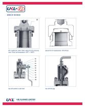
Soft, seated disc (viton; teflon; kalrez) for low pressures Special trim for liquids(series 10O-SV/LIQ) Cap with packed or plain lever Cap with test gag - Safety Valve & Control Valve Division
Open the catalog to page 7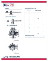
Type "R" counter weighted lever Type"L" counter weighted lever jacket connection Jacketed Body Valves Series SV-100 BODY VALVE HEATING JACKET (Jacket limiting pressure: 10kg/cm2 limiting temperature 18&C.) - Safety Valve & Control Valve Division
Open the catalog to page 8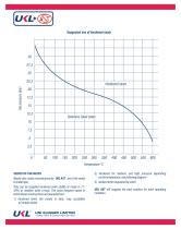
Nozzle-disc seats manufactured by UKL AST are of the metal They can be supplied hardened (with stellite or made in 17- 4PH) or resilient (with o-ring). The most frequent cases in which these constructions are requested are: 1) hardened when the media is dirty, may crystallize 2) hardened for medium and high pressure depending on the temperature, see following diagram 3) resilient when requested by client UKL AST will suggest the best solution for each operating - Safety Valve & Control Valve Division
Open the catalog to page 9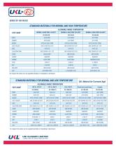
On request the valves can be supplied partially or completely in Aluminium - Safety Valve & Control Valve Division
Open the catalog to page 10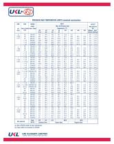
PRESSURE AND TEMPERATURE LIMITS (standard construction) (a) Non API526 center to face dimension - Safety Valve & Control Valve Division
Open the catalog to page 11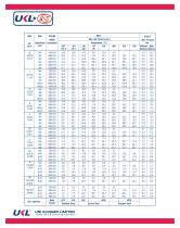
- Safety Valve & Control Valve Division
Open the catalog to page 12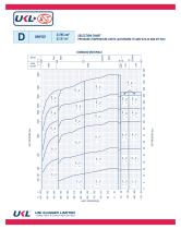
- Safety Valve & Control Valve Division
Open the catalog to page 13
STANDARD MATERIALS
Open the catalog to page 14
STANDARD MATERIALS
Open the catalog to page 15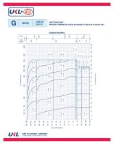
STANDARD MATERIALS
Open the catalog to page 16
- Safety Valve & Control Valve Division
Open the catalog to page 17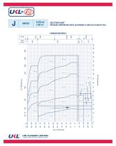
- Safety Valve & Control Valve Division
Open the catalog to page 18
- Safety Valve & Control Valve Division
Open the catalog to page 19
- Safety Valve & Control Valve Division
Open the catalog to page 20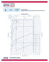
STANDARD MATERIALS
Open the catalog to page 21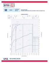
- Safety Valve & Control Valve Division
Open the catalog to page 22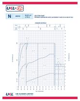
STANDARD MATERIALS
Open the catalog to page 23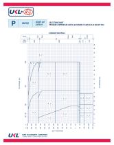
- Safety Valve & Control Valve Division
Open the catalog to page 24
INLET TEMPERATURE - Safety Valve & Control Valve Division
Open the catalog to page 25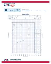
STANDARD MATERIALS
Open the catalog to page 28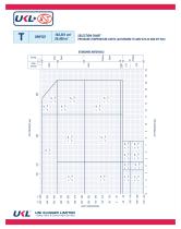
STANDARD MATERIALS
Open the catalog to page 30
The dimensions and the weights are approximate, will not assume any liability for discrepancies between actual dimensions and weights and those shown in this table. Approx. weight - Safety Valve & Control Valve Division
Open the catalog to page 31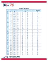
- Safety Valve & Control Valve Division
Open the catalog to page 32
DEFINITIONS (abstract from EN ISO 4126-1) The actual travel of the valve disc away from the closed position. Flow area The minimum cross-sectional flow area (butnotthe curtain area) between inlet and seat which is used to calculate the theoretical flowcapacity, with no deduction for any obstruction. The value of actual flowing capacity (from tests) divided by the theoretical flowing capacity (from calculation). Built-up backpressure The pressure existing atthe outlet of a safety valve caused by flow through the valve and the discharge system. Superimposed back pressure The pressure existing at...
Open the catalog to page 33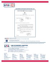
DISCHARGING COEFFICIENTS CERTIFIED SINCE 1976 QUALIFICAZIONE (^f) VALVOLE Dl SICUREZZA ASSOCIAZIONE NAZIONALE PER IL CONTROLLO DELLA COMBUSTIONE DiresioTie Centrals TeCIUc& CGGIttO! ^aalificaiione Valvole di eicwistza, AHT - Seri* 5HD-70CO. Ticto l*arfc* 23 del D.M* Z|/">/T974* che di facolta all'i.lT.C.C, di deterninoxe il coeff iciente d'efflusHo delle valTole di aieureBM Tnedian te l'effrttuazione di prore dirrtte Bv tsnpioaij vitto 11 riaultaxo delle prove effettoate, nel pariodo gmuiaiD- fetobraie 1976f preeBo L'letitnto di Jfctccbir-o del FolitecnicQ di Xilano, en proitrtipi caratiaristici...
Open the catalog to page 34All Uni Klinger Limited catalogs and technical brochures
 Compressed Asbestos Fiber
2 Pages
 Expanded PTFE Sheets
2 Pages
 Spiral Wound Gasket
4 Pages
 Metal jacketted Gasket
2 Pages
 Kammprofile Gasket
2 Pages
 Non-Asbestos Gland Packing
4 Pages
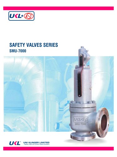 SMU-7000 Safety Relief Valve
34 Pages
 Compressed gasket materials
2 Pages
 Non Asbestos Gland Packings
4 Pages
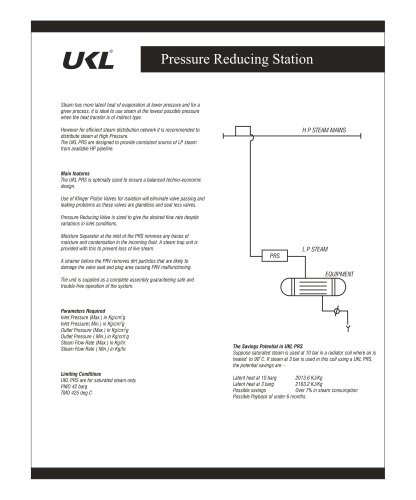 Pressure Reducing Station
2 Pages
 UCT-10 CLEAN STEAM TRAP
1 Page
 LeakTector
1 Page
 ITVS
ITVS4 Pages
 SV 200 & 300 Safety Relief Valve
15 Pages
 AST CV-8000 Control Valve
31 Pages
 High Pressure Valve UHPV
6 Pages
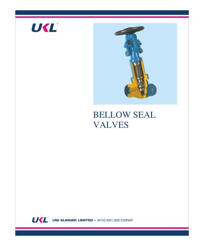 Bellow Seal Valves
20 Pages
 Piston Valves
12 Pages