- Catalogs
- Underhaug AS
- UM 6025 Grass seed drill
UM 6025 Grass seed drill
1 /19Pages
UM 6025 Grass seed drill
1 /19Pages
Catalog excerpts

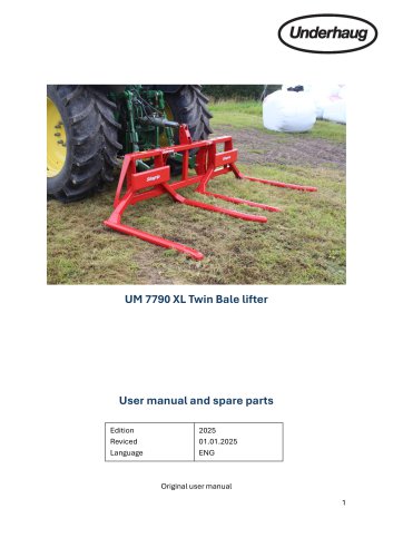
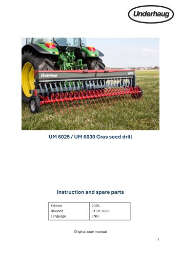
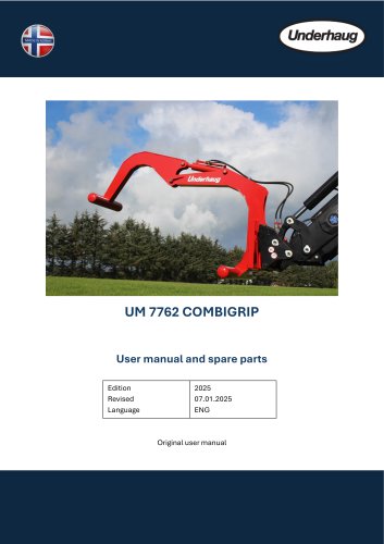
UM 6025 / UM 6030 Gras seed drill Instruction and spare parts Edition Reviced Language Original user manual 1
Open the catalog to page 1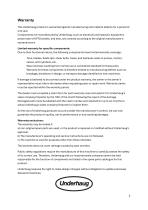
Warranty This Underhaug product is warranted against manufacturing and material defects for a period of one year. Components not manufactured by Underhaug, such as electrical and hydraulic equipment, power take-off (PTO) shafts, and tires, are covered according to the original manufacturer’s warranty terms Limited warranty for specific components: Due to their functional nature, the following components have limited warranty coverage: Tires, blades, blade tips, shear bolts, fuses, and hydraulic seals in pumps, motors, valves, and cylinders, etc. Wear and tear resulting from normal use is considered...
Open the catalog to page 2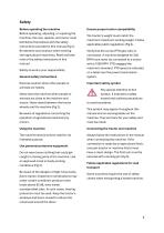
Safety Before operating the machine Before operating, adjusting, or repairing the machine, the user, repairer, and owner must familiarize themselves with the safety instructions provided in this manual (Fig 1). Be attentive and cautious when working with agricultural machinery. Read and take note of the safety instructions in this manual. Safety at work is your responsibility General safety instructions Exercise caution when other people or animals are nearby Never start the machine when people or animals are close to the machine and tractor. Never stand between the tractor wheels and the machine...
Open the catalog to page 4
The tractor engine should be stopped and the ignition key removed before performing any repair work, lubrication, or other maintenance on the machine. (Fig. 6). Ensure that all covers are in good condition and properly mounted. Do not attempt to start the machine until this has been done. Damaged covers should be repaired or replaced immediately. (Fig. 7). Pay special attention to all protective covers related to the power take-off shafts. Replace damaged covers. Safety chains must always be attached to the machine and/or tractor to prevent the protective sleeves from rotating. Be cautious when...
Open the catalog to page 5
When disconnecting the machine and leaving the tractor/machine Set all hydraulic functions to the neutral position when disconnecting the machine. Lower the movable working components to the ground or set them in the transport position and secure them. If the machine is equipped with parking blocks, these should be used. Do not allow children to play or remain near agricultural machines. (Fig. 9). Drive safely Remember, you are responsible – carelessness and negligence can cause serious injury or even death. (Fig. 10). Check the wheel bolts and the connection between the machine and tractor before...
Open the catalog to page 7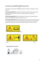
Instructions for UM 6025 UM 6030 Gras seed drill This machine is marked with this replaced. warning sign. If the sign is damaged, it must be Warning sign 220532 (Fig. 1). Caution. Read and understand the instruction manual before using the equipment, and before making adjustments or performing maintenance. Warning sign 220538 (Fig. 2). Due to the high risk of crushing, it is essential to keep people at a safe distance when the equipment is in use. Warning sign 220537 (Fig. 3). When the equipment is mounted on the rear of the tractor or on a loader, ensure no one walks underneath the equipment....
Open the catalog to page 9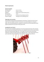
Machine application Technical details Working width: Max. width: Seedbox: Row spacing: No. of seed units: Machine weight: Operating a new machine The seed drill is delivered fully assembled from the factory, except for the rear harrow, which must be installed manually. The machine is securely strapped to a transport pallet. Once the packing straps are released, the machine can be carefully lifted off the pallet and attached to the tractor's three-point hitch. Installing the rear harrow The rear harrow is installed by placing it on the tines located at the back of the machine and securing it with...
Open the catalog to page 10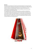
Seed box The seed drill is equipped with a seed box specifically designed for sowing grass seeds. Inside the seed box, a dedicated stirring shaft ensures even distribution of the seeds and prevents clumping. The seeding system operates on a push-shaft principle. The metering rollers have longitudinal rollers and can be adjusted in and out of the seed units to dispense varying seed quantities. The longitudinal shaft, on which the metering rollers are mounted, is adjusted by a screw handle located inside the protective cover on the left side of the seed box. The screw handle is locked into the...
Open the catalog to page 11
The characteristics of a seed variety can change from year to year and are also influenced by humidity. Therefore, it is recommended to perform a calibration test before starting sowing to ensure the desired seeding rate is accurate. We always recommend conducting a calibration test! 1. The adjustment handle is located at the end of the seed box and features a scale ranging from 0-21. Each turn of the handle corresponds to a 3 mm adjustment of the metering rollers. Turning the handle clockwise decreases the seed rate, while turning it counterclockwise increases it. 2. Ensure that the gears are...
Open the catalog to page 12
Troubleshooting Adjustment Handle Feels Tight There may be sand or debris in the threads of the adjustment handle or the seed rollers. Clean thoroughly if necessary and apply silicone spray for lubrication. Seed Rate Changes During Sowing Check for play or wear between the seed shaft and the adjustment handle. If needed, adjust by adding an extra spring washer to eliminate slack. Uneven Output from a Single Seed Unit This should not typically occur, as the seed rollers are factory-adjusted. However, a seed roller may shift due to impact or vibration. If a roller is slightly out of position, adjust...
Open the catalog to page 13
Boom welded UM6030 Boom welded UM6025 Drive wheel mount UM6030 Drive wheel mount UM6025 Pendulum arm Beam for rear harrow UM6030 Beam for rear harrow UM6025 Drive wheel axle Wheel axle left Wheel 4.80/4.00-8 COMPLETE Brace Seed box COMPLETE UM6030 (see figure 19) Seed box COMPLETE UM6025 (see figure 19) Drawbar bolt Parking foot Wheel bolt Double sprocket Bearing housing Suspension shaft Drop tube Hose clamp 25-40 mm Crank handle welded Retaining ring I52 Mounting bracket Tine Washer for tines Locknut M12 Chain link 1/2’’ x 5/16, 5.5 links Drive chain 1/2’’ x 5/16, 43 links Chain lock 1/2’’ x...
Open the catalog to page 15All Underhaug AS catalogs and technical brochures
 GRS 300 simple roller
15 Pages
 Combigrip, UM -7762
15 Pages
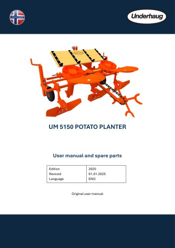 UM 5150 – 2-row potato planter
23 Pages
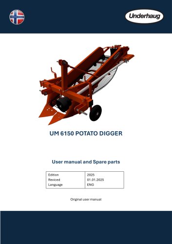 UM 6150 – Elevator digger
25 Pages
 Globus Stone picker model SB
27 Pages
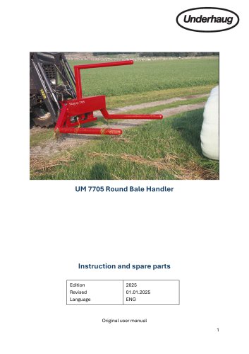 Silagrip UM-7705
19 Pages
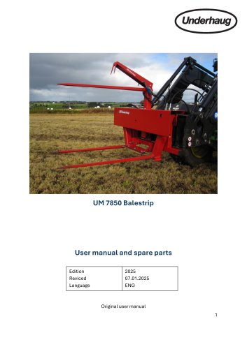 BaleStrip, UM-7850
17 Pages
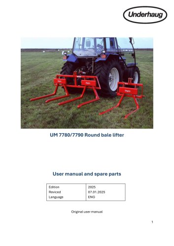 Bale lifter, UM-7780
15 Pages
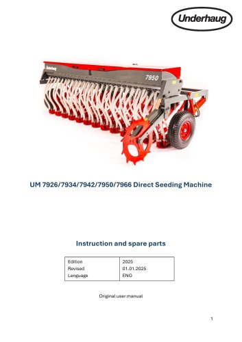 UM 7926
32 Pages
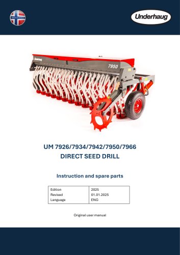 UM 7966
33 Pages
 GTF 250 Globus snow blower
29 Pages
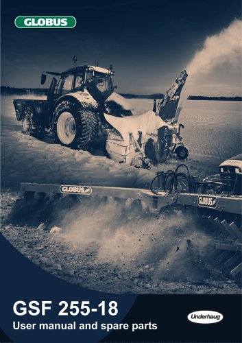
 Globus snow blower GSF 255
30 Pages
 GTF 235 Globus snow blower
32 Pages
 Globus snow blower GTF 255
30 Pages
 Globus snow blower GSF 245
28 Pages
 GTF 2750
28 Pages
 Underhaug-Product-Catalog
25 Pages