Non-contact Flange Detecting System FA

Non-contact Flange Detecting System FA
The Uhing non-contact flange detecting system (FA) automates the correction of reversing points in rolling ring drives, enhancing efficiency and reducing operational costs in industrial applications by eliminating manual adjustments during spool changes or winding processes.
The system employs a sensor (light barrier) to detect coil flanges and trigger the reversal of the traversing unit. As the coil fills and the traversing shaft speed decreases, the stroke length is reduced. A PLC can compensate for this reduction, ensuring consistent performance.
- Power Supply: 85 - 264 V A.C., 47 - 63 Hz
- Compressed Air: 4 bar
- Uhing Rolling Ring traverse with pneumatic reversal mechanism
- Load carrier for sensors and material guide systems
- Light barrier with adjustable lead and telescoping swivel arm
- Relay controller for constant shaft speed
- Optional PLC for variable shaft speed control
The system is based on the Uhing rolling ring drive, converting constant shaft rotation into a traversing motion. It features a pneumatic system activated by a light barrier, which is interrupted by spool flanges to trigger reversal, automatically adjusting to spool variations and adapting reversal points.
- Constant traversing speed with a drive motor and bistable relay controller.
- Synchronization with decreasing coil speed using a belt drive, eliminating the need for a separate motor.
- Optional PLC for a standstill phase to prevent material dropping into gaps.
- Electric: 230 VAC, 50/60 Hz
- Pneumatic: 4.5 to 6 bar
- Mechanical: Proper alignment of the swivel arm and light barrier with the coil axis is required.
Ensure all connections are established. The system should switch over when the light beam is interrupted. Adjustments may be needed if the system does not operate as expected.
- Basic: Adjust the slide to match the flange diameter.
- Fine: Adjust the swivel arm angle for precise traversing stroke.
- Different flange diameters: Adjust by displacing the slide without changing the stroke setting.
The relay controller allows for time adjustments between flange detection and reversal, ensuring smooth operation and preventing errors during switching.
The document describes a bistable relay controller used in systems with constant speed and a separate drive motor. It alternates a 24 VDC voltage at two output terminals, switching based on a control signal at input E1. The relay retains its last position when de-energized.
1. Time Adjustment: The time 'ta' can be adjusted from 0 to 2 seconds using a 1 MOhm potentiometer. After 'ta' expires, the relay switches, changing the solenoid valve output from 24 VDC to 0 V or vice versa. Time 'tb' is adjustable from 0.2 to 2 seconds and starts after 'ta'.
2. PLC Operation: The PLC records speed changes on the traversing shaft and delays the switchover pulse to maintain constant traversing width. An optional pulse counter can be used for precise control.
3. Testing Inputs and Outputs: Set the PLC to 'RUN' mode to check signal status via LEDs. Inputs include speed capturing and light barrier interruption.
1. Light Barrier Sensor: Ensure proper installation and sensitivity adjustment as per the manufacturer's instructions.
2. Function Test: Verify the system by moving the traversing system to the middle and checking the output changes when the light barrier is interrupted.
Details on electrical connections for the PLC and relay controller are provided, including terminal designations and voltage requirements.
Contact details for worldwide service and further technical support are available on the Uhing website.
Catalog excerpts
1. General information Your Benefit: -No readjusting of reversal points after spool change-No readjusting during winding -Easy to install -Low price The Uhing non-contact FA flange detectingsystem provides a cost-effective means to automate required corrections of rolling ring dri- ve reversing points tried and tested in conti- nuous industrial application.The traversing system incessantly distributingthe material between the spool flanges is only rarely regarded as a cost factor. This only occurs when a conversion to new material dia- meters or coil widths is necessary. The setting then remains...
Open the catalog to page 2
Abb. / Fig. 1 Power requirements: Power supply:85 - 264 V A.C., 47 - 63 Hz Compressed Air:4 bar Funktion: Ein Sensor (Lichtschranke) erfat die Spulen- flansche und leitet die Bewegungsumkehr der Verlegung ein. Nimmt die Drehzahl der Verlege- welle mit zunehmendem Fllgrad der Spule ab, verkrzt sich der Hub, da die Umschaltzeit kon- stant bleibt. Um diese Hubverkrzung auszu- gleichen, kann eine SPS mitgeliefert werden. Function: A sensor (light barrier) detects the coil flanges and trips the reversal of the traversing unit. When the speed of the traversing shaft decrea- ses proportional to the...
Open the catalog to page 3
3. Variants3.1 Usually the FA is operated at constant tra-versing speed 3.2 The traversing system is driven by the tra-versing shaft via a belt drive at during winding. This traversingsystem variant features a drive motor of its own and a bistable relay controller allowing the time between flange detection and reversing impulse to be adjusted. For notes on the relay controller refer to item 7.1. 2. Description 3.3 To prevent profiled material from droppinginto the gap between the last winding and the flange a brief stop of the traversing system before reversal is often useful. For this purpose...
Open the catalog to page 4
4. Anschlsse4.1 Elektrisch: 4. Connections4.1 Electric: Betriebsspannung 230 VAC, 50/60 Hz. Operating voltage 230 VAC, 50/60 Hz. 4.2 Pneumatisch 4.2 Pneumatic (Abb.2):4,5 bis 6 bar. (Fig. 2): 4.5 to 6 bar. > Abb.2:pneumatisches Anschluschema f쟼r FAFig.2:Pneumatic connection for FA size="-1">
Open the catalog to page 5
4.3 Mechanic (Fig. 3):Install the traversing system such that the swi-velarm shaft (1) of the light barrier (2) points towards the coil axis (3). Variant 3.2 also requires a connection between winding and traversing shaft by means of a toothed belt or similar. > 4.3 Mechanisch (Abb.3):Die Verlegung muss so eingebaut werden, dassdie Achse des Schwenkarms (1) der Licht- schranke (2) auf die Spulenachse (3) weist. Bei Variante 3.2 ist auerdem die Verbindung von Wickel- und Verlegewelle mittels Zahnriemen o.ߤ. erforderlich. > Abb. / Fig. 3 Abb. / Fig. 4 size="-1">
Open the catalog to page 6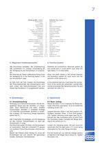
5. Function Control Establish all connections. Reversal system (6)and swivel arm (1) must switch over when the light beam (17) is interrupted.When the shaft rotates in the normal directionthe traversing system (5) must move into the direction of the swivel arm. In the adverse case you must swap the connec-tions of the swivel arm pneumatic cylinder after having unscrewed the clamping screws (16) and removed the slide (11). 6. Adjustments6.1 Basic setting Adjust the slide (11) so it matches the flange dia- meter (18) of the used spool. To do so loosen the clamping screw (16). Largest diameter:...
Open the catalog to page 7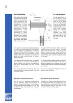
6.2 Fine adjustment Precise adjustment ofthe traversing stroke occurs by changing the angle (a) of the swivel arm (1) during winding. To do so turn the adju- sting screws (8) for each stroke direction accor- ding to the markings. Turning in +ԓ direction results in a stroke increase and morematerial being wound atthe flange. Use the sca- les (15) to verify the changes.To quickly find the optimum setting you mustcarefully observe the first layers in particular. Make small corrections at a time only as too great a change will cause oscillations around the ideal point and prolong the adjustment pro-...
Open the catalog to page 8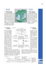
Anschl줼sse: Ausgnge PneumatikLichtschrankensensorsiehe 7.1.3Drehbereich derPotentiometer 360(10-Gang)optional: externesPotentiometer taN/L 230VAC; 50/60 Hz Connections: Exit PneumaticLightbarrier Sensorsee 7.1.3rotation ofPotentiometer 360䰰 (10 gears)Options: externalPotentiometer taN/L 230VAC; 50/60 Hz 0V 12 0V 14 0V E1 +24V ta HSL tb NC NL >
Open the catalog to page 9
7.1.3 Light barrier sensor Exit PNP, darkness switch on E1. Voltage at 0Vand +24V (DC).To install the light barrier and the sensor sensi- vity pay attention to the installation instructionsfrom the sensormanufacturer (are enclose). 7.1.3 Lichtschrankensensor Schaltausgang PNP, dunkelschaltend (Schlie-er) an E1. Betriebsspannung an 0V und +24V (DC). Zur Montage der Lichtleiter an den Lichtschran- kensensor und Empfindlichkeitseinstellung des Schaltzustandes sind die Montagehinweise desSensorherstellers zu bercksichtigen (Beipack). 7.2.1 Testing the inputs and outputs Set PLC to the 'RUN' mode;...
Open the catalog to page 10
Joachim Uhing KG GmbH & Co. Kieler Strae 23 24247 Mielkendorf Telefon+49 (0) 4347-906-0 Telefax+49 (0) 4347-906-40 e-mail: [email protected] http://www.uhing.com Germany > BKInpress 8166 size="-1">
Open the catalog to page 12All UHING catalogs and technical brochures
 Rolling ring drive RG_ARG
74 Pages
 Product Range
24 Pages
 Timing Belt Drive AZ
16 Pages


Archived catalogs
 Rolling Ring Drive
28 Pages
 easylock ® / U-Clip
12 Pages
- Actuator
- Linear actuator
- Electric actuator
- Shaft shaft coupling
- Compact actuator
- Screw actuator
- Rigid coupling
- Extruded aluminum actuator
- Pneumatic actuator
- Sleeve coupling
- Double-acting actuator
- Snap ring
- Hydraulic actuator
- Belt-driven actuator
- Zero-backlash actuator
- Roller guide
- Timing belt actuator
- Shaft collar coupling