SD
1 /6Pages

SD
1 /6Pages
Catalog excerpts
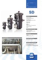
COMPONENTS SUCTION F I LT E R S SD MATERIALS Cover & housing: Anodized aluminium alloy For 61&62 only: Cover: anodized aluminium alloy Housing: steel Bypass valve: Polyammide Seals: NBR Nitrile (FKM on request uoroelastomer) Indicator housing: Brass PRESSURE (ISO 10771-1:2002) Collapse, differential for the lter element (ISO 2941): 1 MPa (10 bar) BYPASS VALVE Setting: 35 kPa (0,35 bar) ± 10% APPLICATION EXAMPLE WORKING TEMPERATURE From -25° to +110° C COMPATIBILITY (ISO 2943:1999) Full with uids: HH-HL-HM-HV-HTG (according to ISO 6743/4) For uids different than the above mentioned, please contact our Sales Department.
Open the catalog to page 1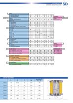
S U C T I O N F I LT E R S ORDERING AND OPTION CHART TYPE F = FILTER COMPLETE B = FILTER HOUSING S D F B F B F B F B F B F B F B - - - - FAMILY NOMINAL SIZE & LENGTH PORT TYPE B = BSP thread N = NPT thread S = SAE thread F = SAE flange 3000 psi, metric screws PORT SIZE - 04 - 04 = 1/2" 06 = 3/4" 08 = 1" 12 = 1" 1/2 20 = 2" 1/2 28 = 3" 1/2 32 = 4" - BYPASS VALVE ELEMENT FAMILY SIZE & LENGTH 06 - 12 - 08 - - - 20 - 28 - 32 W = without A = 35 kPa (0,35 bar) N = NBR Nitrile F = FKM Fluoroelastomer SEALS SEALS N = NBR F = FKM FILTER MEDIA ME = metal wire mesh 60 m MF = metal wire mesh 90 m MG = metal...
Open the catalog to page 3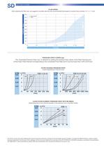
SD S U C T I O N F I LT E R S FLUID SPEED when selecting the filter size, we suggest to consider also the max recommended fluid speed (in suction lines normally 0,1< v < 1 m/s) 500 Recommended range 450 350 0,1< v < 1 m/s FLOW RATE [l/min] 400 300 250 200 150 100 50 0 1/2 3/4 1” 1” 1/2 2” 1/2 3” 1/2 4” PORT SIZE PRESSURE DROP CURVES (∆p) The “Assembly Pressure Drop (∆p)” is obtained by adding the pressure drop values of the Filter Housing and of the Clean Filter Element corresponding to the considered Flow Rate and it must be lower than 3 kPa (0,03 bar). FILTER HOUSING PRESSURE DROP (mainly depending...
Open the catalog to page 4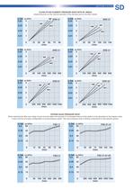
S U C T I O N F I LT E R S CLEAN FILTER ELEMENT PRESSURE DROP WITH M+ MEDIA (depending both on the internal diameter of the element and on the filter media) MF ERD 21 Δp (bar Δp (kPa) ) 0,04 4 0,03 3 0,02 0,01 Δp (bar Δp (kPa) ) 0,04 3 2 0,02 2 1 0,01 ERD 31 4 0,03 SD 1 ME 0 15 30 MG 45 60 l/min Δp (bar Δp (kPa) ) 0,04 3 0,02 2 0,01 1 50 4 0,03 3 0,02 2 0,01 ERD 61 1 0 75 100 125 150 l/min ERD 51 1 0 ME MF MG 100 200 300 400 500 600 l/min Δp (bar Δp (kPa) ) 0,04 4 0,03 3 0,02 MG 50 2 ERD 62 2 0,01 ME MF 25 3 100 150 200 250 300 l/min Δp (bar Δp (kPa) ) MG 4 0,02 MG 0,04 0,03 MF MF Δp (bar Δp...
Open the catalog to page 5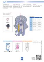
SD S U C T I O N F I LT E R S CLOGGING INDICATOR A visual or electrical indicator allows monitoring of the element condition, and gives an indication of the proper time for replacement. The port for the indicator is a standard feature. STRONG CONSTRUCTION The strong filter housing makes the FSD filters particularly suitable for applications where each component must provide the highest reliability. FLEXIBILITY OF ASSEMBLING A second inlet port, supplied plugged, permits you to easily solve special installation needs. NO LEAKS The end caps with captive O-ring ensure a perfect sealing between filter...
Open the catalog to page 6All UFI HYDRAULIC catalogs and technical brochures
 UFIH_Catalogo_2023
284 Pages
 CSE – SBB
2 Pages
 CBS – SAB
2 Pages
 CBF – FA
2 Pages
 CBE – FA
2 Pages
 CBD – FA
2 Pages
 CBC – TSP
2 Pages
 CBB – FA
2 Pages
 CBA-TM
2 Pages
 FAB
FAB3 Pages
 CLB – LME
2 Pages
 AIR FILTERS
11 Pages
 PC
PC5 Pages
 SA -SB
4 Pages
 MA
MA5 Pages
 PG
PG5 Pages
 CLOGGING INDICATORS
7 Pages
 HYDRO DRY
2 Pages
 UOW
UOW2 Pages
 OF
OF6 Pages
 CBA - CBB - Air breathers
11 Pages
 RH
RH8 Pages
 RG
RG6 Pages
 RF
RF14 Pages
 RD
RD6 Pages
 RC
RC6 Pages
 RB
RB6 Pages
 RA
RA7 Pages
 PM
PM6 Pages
 PL
PL10 Pages
 PH
PH6 Pages
 PE
PE9 Pages
 PD
PD8 Pages
 PB
PB10 Pages
 PA
PA5 Pages
 SE
SE5 Pages
 sc_heavy
5 Pages
 SC
SC5 Pages

Archived catalogs
 CFA-TM
3 Pages
 AIR SENTRY
2 Pages


- Liquid filter
- Filter with cartridge
- Filter cartridge
- Industrial use filter
- Pressure separator filter
- Industrial filter cartridge
- Water pre-filter
- Fine filter cartridge
- Filtration unit
- Water filter cartridge
- Face mask
- Plastic filter cartridge
- General purpose filter cartridge
- Liquids level gauge
- Hydraulic filter
- Basket filter
- VOC-free liquid filtration unit
- In-line filter
- Analog indicator
- Filtering respirator