


PM

PM
Catalog excerpts

Anodized aluminium alloy Bypass valve: Indicator housing: Collapse, differential APPLICATION EXAMPLE BYPASS VALVE WORKING TEMPERATURE Full with fluids: HH-HL-HM-HV-HTG For fluids different than the above mentioned, please contact our Sales
Open the catalog to page 1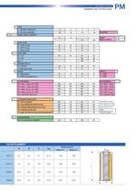
RETURN FILTERS ORDERING AND OPTION CHART FILTER ELEMENT
Open the catalog to page 3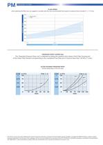
PM P R E S S U R E F I LT E R S FLUID SPEED when selecting the filter size, we suggest to consider also the max recommended fluid speed (in pressure lines normally 5< v < 10 m/s) 400 Recommended range 350 5 < v < 10 m/s FLOW RATE [l/min] 300 250 200 150 100 50 0 1/2” 3/4” 1” PORT SIZE PRESSURE DROP CURVES (∆p) The “Assembly Pressure Drop (∆p)” is obtained by adding the pressure drop values of the Filter Housing and of the Clean Filter Element corresponding to the considered Flow Rate and it must be lower than 120 kPa (1,2 bar). FILTER HOUSING PRESSURE DROP (mainly depending on the port size)...
Open the catalog to page 4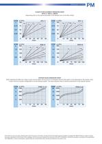
PRESSURE FILTERS CLEAN FILTER ELEMENT PRESSURE DROP (depending both on the internal diameter of the element and on the filter media) BYPASS VALVE PRESSURE DROP When selecting the filter size, these curves must be taken into account if it is foreseen that any flow peak is to be absorbed by the bypass valve, it also must be of proper configuration to avoid pressure peaks. The valve pressure drop is directly proportional to fluid specific gravity. N.B. All the curves have been obtained with mineral oil having a kinematic viscosity 30 cSt and specific gravity 0,9 kg/dm3; for fluids with different...
Open the catalog to page 5
PM P R E S S U R E F I LT E R S CLOGGING INDICATOR A visual or visual-electrical differential indicator is available as an option and allows monitoring of the element conditions, giving an exact indication of the right time to replace the element. CLOGGING INDICATOR For further technical informations and other options see page 182-183. FILTER HOUSING Head and bowl are made by high performance aluminium alloy ensuring the best fatigue resistance. FILTER ELEMENT The filter element is manufactured with filter medias selected in the UFI laboratory and mechanically supported to maintain the highest...
Open the catalog to page 6All UFI HYDRAULIC catalogs and technical brochures
 UFIH_Catalogo_2023
284 Pages
 CSE – SBB
2 Pages
 CBS – SAB
2 Pages
 CBF – FA
2 Pages
 CBE – FA
2 Pages
 CBD – FA
2 Pages
 CBC – TSP
2 Pages
 CBB – FA
2 Pages
 CBA-TM
2 Pages
 FAB
FAB3 Pages
 CLB – LME
2 Pages
 AIR FILTERS
11 Pages
 PC
PC5 Pages
 SA -SB
4 Pages
 MA
MA5 Pages
 PG
PG5 Pages
 CLOGGING INDICATORS
7 Pages
 HYDRO DRY
2 Pages
 UOW
UOW2 Pages
 OF
OF6 Pages
 CBA - CBB - Air breathers
11 Pages
 RH
RH8 Pages
 RG
RG6 Pages
 RF
RF14 Pages
 RD
RD6 Pages
 RC
RC6 Pages
 RB
RB6 Pages
 RA
RA7 Pages
 PL
PL10 Pages
 PH
PH6 Pages
 PE
PE9 Pages
 PD
PD8 Pages
 PB
PB10 Pages
 PA
PA5 Pages
 SE
SE5 Pages
 SD
SD6 Pages
 sc_heavy
5 Pages
 SC
SC5 Pages

Archived catalogs
 CFA-TM
3 Pages
 AIR SENTRY
2 Pages




- Liquid filter
- Filter with cartridge
- Filter cartridge
- Industrial use filter
- Industrial filter cartridge
- Fine filter cartridge
- Water pre-filter
- Filtration unit
- Water filter cartridge
- Plastic filter cartridge
- Face mask
- General purpose filter cartridge
- Liquids level gauge
- Hydraulic filter
- Basket filter
- VOC-free liquid filtration unit
- In-line filter
- Analog indicator
- Filtering respirator