


PG

PG
Catalog excerpts

PG MATERIALS Head: Aluminium alloy Bowl: Steel Bypass valve : NBR Nitrile (FKM - on request uoroelastomer) Seals: NBR Nitrile (FKM - on request uoroelastomer) Indicator housing: Brass PRESSURE (ISO 10771-1:2002) Max working: 5 MPa (50 bar) Fatigue test: 0-5 Mpa (0-50 bar) 1 million cycles Collapse, differential for the lter element (ISO 2941): 1 MPa (10 bar) BYPASS VALVE Setting: 350 kPa (3,5 bar) ±10% WORKING TEMPERATURE From -25° to +110° C COMPATIBILITY (ISO 2943:1999) Full with uids: HH-HL-HM-HV-HTG (according to ISO 6743/4) For uids different than the above mentioned, please contact our Sales Department.
Open the catalog to page 1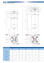
INSTALLATION DRAWING Indicator port (Option C) Indicator port (Option C) Indicator port (Option B) 0 Indicator port (Option B) Indicator port (Option A) Indicator port (Option A)
Open the catalog to page 2
ORDERING AND OPTION CHART ELEMENT F F = FILTER COMPLETE FAMILY, NOMINAL SIZE & LENGTH FAMILY SIZE & LENGTH PORT SIZE (quote D1) 06 = 3/4" 08 = 1" 12 = 1" 1/2 BYPASS VALVE W = without D = bypass valve 3,5 bar FILTER MEDIA FA = fiber 5 m(c) >1.000 FB = fiber 7 m(c) >1.000 FC = fiber 12 m(c) >1.000 FD = fiber 21 m(c) >1.000 CC = cellulose 10 m >2 CD = cellulose 25 m MC = metal wire mesh MD = metal wire mesh ME = metal wire mesh MF = metal wire mesh 76 = differential 2,5 bar, electrical + visual T6 = differential 2,5 bar, electrical with Thermostat 30°C ACCESSORIES W = no indicator port A = indicator...
Open the catalog to page 3
FLUID SPEED when selecting the filter size, we suggest to consider also the max recommended fluid speed (in pressure lines normally 5 < v < 10 m/s). RECOMMENDED FLOW RATES Filter Media Filter Media N.B. All the data have been obtained with mineral oil having a kinematic viscosity 30 cSt and specific gravity 0,9 kg/dm3; for fluids with different features, please consider the factors described in the first part of this catalogue. All the data are obtained from test done at the UFI HYDRAULIC DIVISION Laboratory, according to the specification ISO 3968:2005. In case of discrepancy, please check the...
Open the catalog to page 4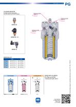
CLOGGING INDICATOR For further technical informations and other options see General Catalogue. Indicator port side (Option C) Differential Indicator port side (Option A) Differential Indicator port side (Option B) Differential FILTER HOUSING FILTER ELEMENT SPARE PARTS ELEMENTS (For filling up see table “Ordering and option chart”) Is this datasheet the latest release? Please check on our website. Technical data subject to variations without prior notice. PG - EN - 07/2014
Open the catalog to page 5All UFI HYDRAULIC catalogs and technical brochures
 UFIH_Catalogo_2023
284 Pages
 CSE – SBB
2 Pages
 CBS – SAB
2 Pages
 CBF – FA
2 Pages
 CBE – FA
2 Pages
 CBD – FA
2 Pages
 CBC – TSP
2 Pages
 CBB – FA
2 Pages
 CBA-TM
2 Pages
 FAB
FAB3 Pages
 CLB – LME
2 Pages
 AIR FILTERS
11 Pages
 PC
PC5 Pages
 SA -SB
4 Pages
 MA
MA5 Pages
 CLOGGING INDICATORS
7 Pages
 HYDRO DRY
2 Pages
 UOW
UOW2 Pages
 OF
OF6 Pages
 CBA - CBB - Air breathers
11 Pages
 RH
RH8 Pages
 RG
RG6 Pages
 RF
RF14 Pages
 RD
RD6 Pages
 RC
RC6 Pages
 RB
RB6 Pages
 RA
RA7 Pages
 PM
PM6 Pages
 PL
PL10 Pages
 PH
PH6 Pages
 PE
PE9 Pages
 PD
PD8 Pages
 PB
PB10 Pages
 PA
PA5 Pages
 SE
SE5 Pages
 SD
SD6 Pages
 sc_heavy
5 Pages
 SC
SC5 Pages

Archived catalogs
 CFA-TM
3 Pages
 AIR SENTRY
2 Pages




- Liquid filter
- Filter with cartridge
- Filter cartridge
- Industrial use filter
- Pressure separator filter
- Industrial filter cartridge
- Fine filter cartridge
- Water pre-filter
- Filtration unit
- Water filter cartridge
- Plastic filter cartridge
- Face mask
- General purpose filter cartridge
- Liquids level gauge
- Hydraulic filter
- Basket filter
- VOC-free liquid filtration unit
- In-line filter
- Analog indicator
- Filtering respirator