OF
1 /6Pages

OF
1 /6Pages
Catalog excerpts

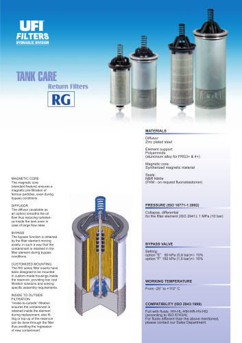
OF MATERIALS Head and covers: Aluminium alloy Bowl: Steel Element Holder: Polyammide OF24 Alluminium Alloy OF3+ and OF4+ Seals: NBR Nitrile FKM Fluoroelastomer on request Indicator housing: Brass PRESSURE (ISO 10771-1:2002) Max working: 1 MPa (10 bar) Test: 1,5 MPa (15 bar) Bursting: 3 MPa (30 bar) Collapse, differential for the lter element: 1 MPa (10 bar) APPLICATION EXAMPLE BYPASS VALVE Setting: 150 kPa (1,5 bar) ± 10% WORKING TEMPERATURE From -25° to +110° C COMPATIBILITY (ISO 2943:1999) Full with uids: HH-HL-HM-HV-HTG (according to ISO 6743/4) For uids different than the above mentioned, please contact our Sales Department.
Open the catalog to page 1
INSTALLATION DRAWING N.B. Mounting brackets optional N.B. Mounting brackets optional FILTER HOUSING PORT SIZE
Open the catalog to page 2
OFF-LINE FILTERS ORDERING AND OPTION CHART
Open the catalog to page 3
FLUID SPEED when selecting the filter size, we suggest to consider also the max recommended fluid speed (in off-lines normally 1,5 < v < 4 m/s) Recommended range FLOW RATE [l/min] PORT SIZE PRESSURE DROP CURVES (∆p) The “Assembly Pressure Drop (∆p)” is obtained by adding the pressure drop values of the Filter Housing and of the Clean Filter Element corresponding to the considered Flow Rate and it must be lower than 50 kPa (0,5 bar). FILTER HOUSING PRESSURE DROP (mainly depending on the port size) N.B. All the curves have been obtained with mineral oil having a kinematic viscosity 30 cSt and specific...
Open the catalog to page 4
O F F - L I N E F I LT E R S CLEAN FILTER ELEMENT PRESSURE DROP WITH F+, C+ AND ME MEDIA (depending both on the internal diameter of the element and on the filter media) BYPASS VALVE PRESSURE DROP When selecting the filter size, these curves must be taken into account if it is foreseen that any flow peak is to be absorbed by the bypass valve, it also must be of proper configuration to avoid pressure peaks. The valve pressure drop is directly proportional to fluid specific gravity. N.B. All the curves have been obtained with mineral oil having a kinematic viscosity 30 cSt and specific gravity...
Open the catalog to page 5
CLOGGING INDICATOR A differential clogging indicator allows monitoring filter element and provides the exact time for replace the element. BYPASS VALVE The bypass function is obtained by the filter element moving axially, in such a way that the contaminant is retained in the filter element during bypass. FILTER ELEMENT “LONG LIFE” Filter elements are manufactured with a large surface area, in order to ensure a high dirt holding capacity. Inside to outside filtration ensures the contaminant is retained inside the element during replacement. FLEXIBILITY OF INSTALLATION Outlet port should be rotate...
Open the catalog to page 6All UFI HYDRAULIC catalogs and technical brochures
 UFIH_Catalogo_2023
284 Pages
 CSE – SBB
2 Pages
 CBS – SAB
2 Pages
 CBF – FA
2 Pages
 CBE – FA
2 Pages
 CBD – FA
2 Pages
 CBC – TSP
2 Pages
 CBB – FA
2 Pages
 CBA-TM
2 Pages
 FAB
FAB3 Pages
 CLB – LME
2 Pages
 AIR FILTERS
11 Pages
 PC
PC5 Pages
 SA -SB
4 Pages
 MA
MA5 Pages
 PG
PG5 Pages
 CLOGGING INDICATORS
7 Pages
 HYDRO DRY
2 Pages
 UOW
UOW2 Pages
 CBA - CBB - Air breathers
11 Pages
 RH
RH8 Pages
 RG
RG6 Pages
 RF
RF14 Pages
 RD
RD6 Pages
 RC
RC6 Pages
 RB
RB6 Pages
 RA
RA7 Pages
 PM
PM6 Pages
 PL
PL10 Pages
 PH
PH6 Pages
 PE
PE9 Pages
 PD
PD8 Pages
 PB
PB10 Pages
 PA
PA5 Pages
 SE
SE5 Pages
 SD
SD6 Pages
 sc_heavy
5 Pages
 SC
SC5 Pages

Archived catalogs
 CFA-TM
3 Pages
 AIR SENTRY
2 Pages