- Catalogs
- UFI HYDRAULIC
- CLB – LME
CLB – LME
1 /2Pages

CLB – LME
1 /2Pages
Catalog excerpts

CLB-LME ACCESSORIES DESCRIPTION Float switches FLOAT SWITCHES Electrical level indicators, an electrical signal is activated when the minimum (or maximum) oil level is reached. The REED switch has SPDT contacts. N.B. the float switch must be mounted at min 50 mm from ferrous walls. Max oil viscosity 150 cSt. MATERIALS Tank connection: Anodized aluminium Rod: Stainless steel Float: Polyammide COMPATIBILITY (ISO 2943 ) Full with fluids HH-HL-HM-HV-HTG (according to ISO 6743/4). For fluids different than the above mentioned, please contact our Customer Service. WORKING TEMPERATURE HYDRAULIC DIAGRAM Is this datasheet the latest release? Please check on our website.
Open the catalog to page 1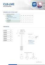
ORDERING AND OPTION CHART C ELECTRICAL DATA SPDT Reed switch Max load AC up to 48V-0,5A Max load DC up to 48V-0,5 A Connector DIN 43650 Protection DIN 40050: IP65
Open the catalog to page 2All UFI HYDRAULIC catalogs and technical brochures
 UFIH_Catalogo_2023
284 Pages
 CSE – SBB
2 Pages
 CBS – SAB
2 Pages
 CBF – FA
2 Pages
 CBE – FA
2 Pages
 CBD – FA
2 Pages
 CBC – TSP
2 Pages
 CBB – FA
2 Pages
 CBA-TM
2 Pages
 FAB
FAB3 Pages
 AIR FILTERS
11 Pages
 PC
PC5 Pages
 SA -SB
4 Pages
 MA
MA5 Pages
 PG
PG5 Pages
 CLOGGING INDICATORS
7 Pages
 HYDRO DRY
2 Pages
 UOW
UOW2 Pages
 OF
OF6 Pages
 CBA - CBB - Air breathers
11 Pages
 RH
RH8 Pages
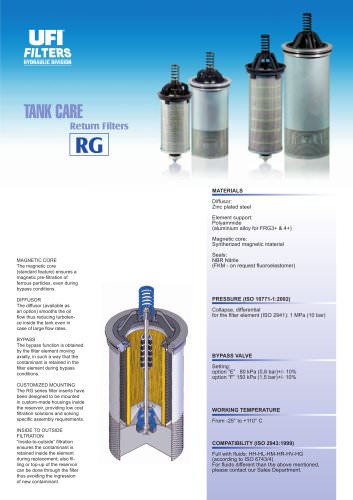
 RG
RG6 Pages
 RF
RF14 Pages
 RD
RD6 Pages
 RC
RC6 Pages
 RB
RB6 Pages
 RA
RA7 Pages
 PM
PM6 Pages
 PL
PL10 Pages
 PH
PH6 Pages
 PE
PE9 Pages
 PD
PD8 Pages
 PB
PB10 Pages
 PA
PA5 Pages
 SE
SE5 Pages
 SD
SD6 Pages
 sc_heavy
5 Pages
 SC
SC5 Pages

Archived catalogs
 CFA-TM
3 Pages
 AIR SENTRY
2 Pages


- Liquid filter
- Filter with cartridge
- Filter cartridge
- Pressure separator filter
- Industrial use filter
- Industrial filter cartridge
- Water pre-filter
- Fine filter cartridge
- Filtration unit
- Water filter cartridge
- Face mask
- Plastic filter cartridge
- General purpose filter cartridge
- Basket filter
- Liquids level gauge
- Hydraulic filter
- VOC-free liquid filtration unit
- In-line filter
- Analog indicator
- Filtering respirator