UBX-21006395 - R07 C1-Public www.u-blox.com Indoor positioning demo system
1 /23Pages
UBX-21006395 - R07 C1-Public www.u-blox.com Indoor positioning demo system
1 /23Pages
Catalog excerpts

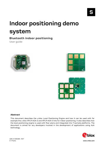
Indoor positioning demo system Bluetooth indoor positioning User guide Abstract This document describes the u-blox Local Positioning Engine and how it can be used with for example the u-blox XPLR-AOA-2 and XPLR-AOA-3 kits for indoor positioning. It also describes how the local positioning engine is used with floor plans and integrated into Traxmate platforms. The document is aimed for any developers involved in the development of applications using AoA technology.
Open the catalog to page 1
Indoor positioning demo system - User guide Subtitle Bluetooth indoor positioning Document type User guide This document applies to the following products: Product name NINA-B4 XPLR-AOA-2 XPLR-AOA-3 Local Positioning Engine v3.0 is only compatible with u-locateEmbed v3.0 and above. Be sure to upgrade all anchor points. u-blox or third parties may hold intellectual property rights in the products, names, logos, and designs included in this document. Copying, reproduction, or modification of this document or any part thereof is only permitted with the express written permission of u-blox. Disclosure...
Open the catalog to page 2
Indoor positioning demo system - User guide
Open the catalog to page 3
Indoor positioning demo system - User guide This document describes the u-blox XPLR-AOA-2 and XPLR-AOA-3 kits and explains how to use them for indoor positioning. The kits builds on the Bluetooth indoor direction-finding technology from u-blox and includes a positioning algorithm and web-based GUI for configuring the system and tracking beacons. To understand the technology underlying direction-finding systems, refer to the Bluetooth Indoor Positioning product page [11].
Open the catalog to page 4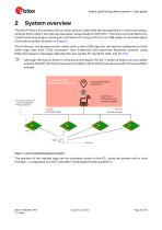
Indoor positioning demo system - User guide System overview The XPLR-AOA-2 kit consists of four u-blox anchor nodes that can be positioned in most room areas, while 4x XPLR-AOA-3 kits yield an equivalent setup based on ANT-B10. The kits are connected to the Local Positioning Engine running on a Windows PC using a Wi-Fi or an USB cable. An example setup of the demo system is shown in Figure 2. Out of the box, the system anchor nodes track u-blox C209 tags but can also be configured to track other tags that emit CTEs (Constant Tone Extension) and advertise Bluetooth content using Eddystone beacon...
Open the catalog to page 5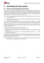
Indoor positioning demo system - User guide Installation of anchor points 3.1 Placement and configuration of anchors Anchors can be connected through the UART interface using USB cables but can also connect over Wi-Fi/UDP. To connect anchors through the UART interface using USB cables, make sure the baud rate is configured to 115200bps. To connect anchors over UDP, the UDP server must be started in the “Utils” tab. To learn how the anchor nodes can be configured to connect to the Local Positioning Engine over UDP, see also the XPLR-AOA kits user guides [7] [10]. UDP is a connectionless protocol,...
Open the catalog to page 6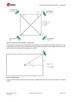
Indoor positioning demo system - User guide Figure 2: Anchor placement and angles in a square layout If your layout is not square but rectangular for example, you can calculate the angles using the normal trigonometry formulas. Figure 3 shows the mathematical calculation of the angle, but you can also use a protractor to measure the angles if you prefer. Figure 3: Angle calculation It is also perfectly fine to just place the anchors in alignment with the corner with angles in multiples of 45°. Installation of anchor points
Open the catalog to page 7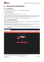
Indoor positioning demo system - User guide 4.1 Installation The positioning engine is delivered as a zip container file that includes: • The server executable • Some example floor plans To install the engine, extract and then run the server.exe file. To access the positioning engine, open a web browser tab with the address http://localhost:5000, where the user interface for configuration and running the local positioning engine can be found. Google Chrome is the preferred browser for the web-based user interface. 4.2 Anchor connection The anchor nodes can be connected to the PC using either...
Open the catalog to page 8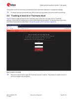
Indoor positioning demo system - User guide The system confirms how many connected anchors have been detected in subsequent dialogs. To detect anchors connected over UDP at least one tag needs to be active and transmitting. 4.3 Tracking in local UI or Traxmate cloud Figure 5 shows a login prompt for the Traxmate cloud, where you can sign up for a Traxmate account. This is the first dialog that is shown when starting the system. To use the cloud, log in here and follow the procedures described in Using the system with Traxmate integration. Figure 5: System start dialog Password requirements apply...
Open the catalog to page 9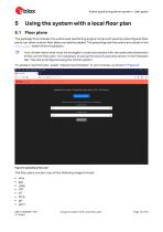
Indoor positioning demo system - User guide Using the system with a local floor plan 5.1 Floor plans The package that includes the u-blox local positioning engine comes with several preconfigured floor plans, but other custom floor plans can also be added. The preconfigured floor plans are stored in the floor_plans folder of the installation. Your chosen demo area must be arranged in close accordance with the scale and dimensions of the current floor plan. It is necessary to set up the size of used area shown in the Floorplan tab. The size is configured using the metric system. To upload a new...
Open the catalog to page 10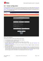
Indoor positioning demo system - User guide Having uploaded your floor plan, you must then place the anchors in the model. Follow the placement and configuration of anchors you chose earlier and configure the anchors one-by-one as, as shown in Figure 7.The connected anchor points are automatically detected and listed in the drop-down list in the Anchor configuration view. Set these parameters to place and configure the anchors: • X: X coordinate of anchor, related to map. Set in meters. • Y: Y coordinate of anchor. Set in meters. • Z: Z coordinate, that is height of anchor over the floor. Set...
Open the catalog to page 11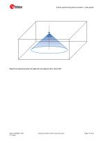
Indoor positioning demo system - User guide Figure 8: surveyed area when min angle and max angle are set to -45 and 45° Using the system with a local floor plan
Open the catalog to page 12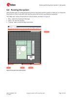
Indoor positioning demo system - User guide 5.3 Running the system After the floor plan is configured and the anchors have been set the system is ready to run. Press the Play button in the UI and verify that the floor plans and anchors are placed as expected. The “Map view” shows three buttons in the UI footer, as shown in Figure 9: • Play – starts the tracking of the tags • Down – for internal use only • Tracing – adds a trace the tag movements Figure 9: Floor plan with anchors placed Using the system with a local floor plan
Open the catalog to page 13All U-blox AG catalogs and technical brochures
 NORA-B2 series
43 Pages
 ANN-MB5
11 Pages
 NORA-W36 series
31 Pages
 LEXI-R520
40 Pages
- Real-time software
- Wireless module
- GNSS antenna
- High-performance software
- Compact antenna
- External antenna
- Architecture software
- Microcontroller
- Multi-band antenna
- Positioning software
- GNSS module
- GPS GNSS module
- GLONASS GNSS module
- Active antenna
- GALILEO GNSS module
- QZSS GNSS module
- BeiDou GNSS module
- Bluetooth WiFi module
- Bluetooth software
- Communication microcontroller