LEXI-R520
1 /40Pages

LEXI-R520
1 /40Pages
Catalog excerpts
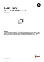
LEXI-R520 Ultra-small LTE-M / NB-IoT module Data sheet Abstract Technical data sheet describing the ultra-small LEXI-R520 multi-band LTE-M / NB-IoT modules, based on the latest u-blox UBX-R52 chipset, integrating cellular modem and A-GPS technology, delivering data connectivity alongside satellite positioning in the compact LEXI form factor.
Open the catalog to page 1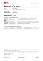
^bloxDocument information Title LEXI-R520 Document type Data sheet Product status Corresponding content status Functional sample Draft For functional testing. Revised and supplementary data will be published later. In development / Objective specification T arget values. Revised and supplementary data will be published later. Engineering sample Advance information Data based on early testing. Revised and supplementary data will be published later. Initial production Early production information Data from product verification. Revised and supplementary data may be published later. Mass production...
Open the catalog to page 2
^blox Contents
Open the catalog to page 3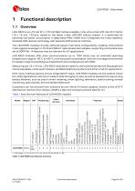
Qiblox1 Functional description1.1 Overview LEXI-R520 is an LTE Cat M1 / LTE Cat NB2 module available in the ultra-small LEXI LGA form factor (16 x 16 mm, 133-pin), based on the latest u-blox UBX-R52 cellular chipset. It is optimized for extremely low power consumption in deep-sleep PSM / eDRX and it integrates the u-blox SpotNow Assisted-GPS receiver technology with separate GPS antenna interface. The LEXI-R520 modules provide software-based multi-band configurability enabling international multi-regional coverage in LTE-M and NB-IoT radio access technologies, supporting a comprehensive set of...
Open the catalog to page 5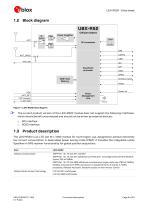
Power Amplifier Cellular chipset Base Band processor SDIO GPIOs Antenna tuner ADC ANT_DET VCC (supply) V_INT (I/O) Power Management Unit 32 kHz Figure 1: LEXI-R520 block diagram The current product version of the LEXI-R520 module does not support the following interfaces, which should be left unconnected and should not be driven by external devices: o o SPI interface SDIO interface 1.3 Product description The LEXI-R520 is an LTE Cat M1 / NB2 module for multi-region use, designed to achieve extremely low current consumption in deep-sleep power saving mode (PSM). It includes the integrated u-blox...
Open the catalog to page 6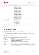
^bloxItem LEXI-R520 Cellular operating bands LTE FDD band 1 (2100 MHz) LTE FDD band 2 (1900 MHz) LTE FDD band 3 (1800 MHz) LTE FDD band 4 (1700 MHz) LTE FDD band 5 (850 MHz) LTE FDD band 8 (900 MHz) LTE FDD band 12 (700 MHz) LTE FDD band 13 (750 MHz) LTE FDD band 18 (850 MHz) LTE FDD band 19 (850 MHz) LTE FDD band 20 (800 MHz) LTE FDD band 25 (1900 MHz) LTE FDD band 26 (850 MHz) LTE FDD band 28 (700 MHz) LTE FDD band 66 (1700 MHz) LTE FDD band 71 (600 MHz) LTE FDD band 85 (700 MHz) Cellular power class LTE power class 3 (23 dBm) Cellular data rate LTE category M1: Assisted-GPS receiver type u-blox...
Open the catalog to page 7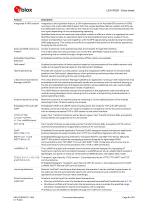
Integrated A-GPS receiver Integrated u-blox SpotNow feature, a SW implementation of an Assisted GPS receiver (A-GPS) running on the u-blox UBX-R52 chipset. With the unique SpotNow feature, cellular and GPS use two dedicated antennas. Internally to the module, the radio resources are switched between the two inputs depending on the corresponding operating. SpotNow feature can be used when the cellular modem is offline or when it is registered to a cell. SpotNow feature relies on assistance data to be downloaded at least every couple of hours. Cellular and SpotNow may work together, with the GPS...
Open the catalog to page 8
Last gasp In case of power supply outage the cellular module can be configured through the +ULGASP AT command to send an alarm notification to a remote entity. Network indication GPIO configured to indicate the network status: registered home network, registered roaming, data call enabled, no service. The feature can be enabled through the +UGPIOC AT command. Antenna detection The ANT_DET pin provides antenna presence detection capability, evaluating the resistance from the ANT pin to GND by means of an external antenna detection circuit implemented on the application board. The feature can be...
Open the catalog to page 9
Module supply input (VCC) LEXI-R520 modules must be supplied through the VCC pins by a proper external DC power supply providing a nominal voltage within the normal operating range (see Table 11). Voltage must be stable, because during operation the current drawn from VCC may vary significantly, based on the power consumption profile of the LTE Cat M1 and LTE Cat NB2 radio access technologies. The three VCC pins of LEXI-R520 modules are internally connected to both the internal power amplifier and the internal power management unit, which integrates voltage regulators generating all the internal...
Open the catalog to page 10
^blox2.3 System functions2.3.1 Module power-on When the LEXI-R520 modules are not powered, they can be switched on as following: • Applying a voltage at the VCC module supply input within the operating range (see Table 11) When the LEXI-R520 modules are in power-off mode (i.e. switched off, but with a valid voltage present at the VCC module supply input within the operating range reported in Table 11), they can be switched on as follows: • Forcing a low level at the PWR_ON input pin, which is normally set high by an internal pull-up, for a valid time period (see section 4.2.8, module switch on)....
Open the catalog to page 11
Module reset LEXI-R520 modules can be reset (re-booted), saving current parameter settings in the module’s non-volatile memory and performing a proper network detach, by: • AT+CFUN=16 command. This causes a graceful software reset of the module. An abrupt software reset of the module is executed by applying a low pulse at the RESET_N input pin, which is normally set high by an internal pull-up, for a valid time period (see section 4.2.9). The current parameter settings are not saved in the module’s non-volatile memory and a proper network detach is not performed. The RESET_N line is intended...
Open the catalog to page 12
Qiblox • Variant 1, consists of a single UART interface that supports AT commands, data communication, multiplexer protocol functionality, FW update by means of FOAT or by means of the u-blox EasyFlash tool, and provides the following lines: o Data lines (RXD as output, TXD as input), o Hardware flow control lines (CTS as output, RTS as input), o Modem status and control lines (DTR as input, DSR as output, DCD as output, RI as output) • Variants 2, 3 and 4, consists of two UART interfaces plus ring indication and DTR functions: o First primary UART interface supports AT commands, data communication,...
Open the catalog to page 13All U-blox AG catalogs and technical brochures
 NORA-B2 series
43 Pages
 ANN-MB5
11 Pages
 NORA-W36 series
31 Pages
- Real-time software
- Wireless module
- GNSS antenna
- High-performance software
- Compact antenna
- Architecture software
- Microcontroller
- Multi-band antenna
- Positioning software
- GNSS module
- GPS GNSS module
- GLONASS GNSS module
- Active antenna
- GALILEO GNSS module
- QZSS GNSS module
- BeiDou GNSS module
- Bluetooth WiFi module
- Bluetooth software
- Communication microcontroller