
Catalog excerpts

Worldwide www.tyco-fire.com Contacts Model RM-2 Riser Manifold General Description The TYCO Model RM-2 Riser Manifold features the necessary waterflow alarm, pressure gauge, alarm test orifice, drain, sight glass and check valve equipment in a single assembly for use in National Fire Protection Association (NFPA) standard NFPA 13* compliant commercial sprinkler systems. The riser manifold is available in a 2 in. to 6 in. range of sizes, and provides a cost effective and easy transition arrangement to control valves and system piping. The riser manifold may be installed in either a horizontal or vertical orientation, for both single sprinkler rises and floor control in high-rises. A TYCO Model TD-2 Test and Drain Valve installed on the riser manifold as shown in Figure 2 provides a simplified means for testing of waterflow alarm devices and draining for feed mains. The pressure relief valve, integrated in the TYCO Model TD-2 Test and Drain Valve, has an adjustable range of 100 psi (6,9 bar) to 310 psi (21,4 bar). Excess system pressure is exhausted internally through the TD-2 valve’s drain outlet. For more information about the Model TD-2 Test and Drain Valve, refer to Technical Data Sheet TFP965. * Although the Riser Manifold described in this technical data sheet is intended for the NFPA 13 sprinkler systems, it may be used for NFPA 13D or 13R residential sprinkler systems, where a test orifice of 2.8K or 4.2K is acceptable. NOTICE The TYCO Model RM-2 Riser Manifold described herein must be installed and maintained in compliance with this document, as well as with the applicable standards of the NATIONAL FIRE PROTECTION ASSOCIATION (NFPA), in addition to the standards of any other authorities having jurisdiction. Failure to do so may impair the performance of these devices. The owner is responsible for maintaining their fire protection system and devices in proper operating condition. Contact the installing contractor or product manufacturer with any questions. Technical Data Approvals UL and C-UL Listed FM Approved Components Listed by California State Fire Marshall Note: Any alteration to the assembly voids UL approval and the product warranty. Maximum Working Pressure 300 psi (20,7 bar) Friction Loss See Table A Test Orifice IMPORTANT Refer to Technical Data Sheet TFP2300 for warnings pertaining to regulatory and health information.
Open the catalog to page 1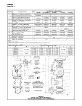
Part Description Model BFV-300 Butterfly Valve, G x G Figure 716 Reducing Grooved Coupling Figure 577 Rigid Grooved Coupling Figure 577 Rigid Grooved Coupling Groove x Groove Nipple, Flow Switch 1 Waterflow Alarm Switch, Potter VSR 1 Model CV-1FR Riser Check Valve 1 Groove x Groove x Thread Tee, TD-2 1-1/4” x 2.8K Orifice 1 Model TD-2 Test and Drain Valve 2” x 4.2K Orifice 1 Model RM-2 Identification Tag 1 Water Pressure Gauge, 300 psi/2000 kPa 1 1/4" Gauge Test Valve 1 Pipe Nipple, Galvanized 2 Pipe Plug, Galvanized 1 Pipe Plug, Galvanized NOTES 1. CH = Common Hardware 2. Refer to...
Open the catalog to page 2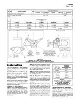
Part Description 1 Pipe Nipple, Galvanized 1 Elbow, Galvanized NOTES 1. CH = Common Hardware RISER MANIFOLD SYSTEM DRAIN CONNECTION DRAIN OUTLET TEST AND DRAIN VALVE (SHOWN TO ILLUSTRATE ALTERNATE INSTALLATION LOCATION ONLY, NOT INCLUDED IN KIT) FIGURE 2 MODEL TD-2 TEST AND DRAIN VALVE ALTERNATE INSTALLATION KIT ARRANGEMENT Installation The TYCO Model RM-2 Riser Manifold must be installed in accordance with this section. The Model RM-2 Riser Manifold may be installed either horizontally or vertically. Note: Where applicable pipe thread sealant must be applied sparingly. Use of a...
Open the catalog to page 3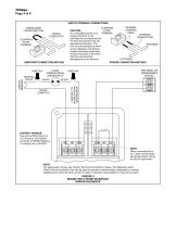
TFP964 Page 4 of 6 SWITCH TERMINAL CONNECTIONS SEVERED CLAMPING STRIPPED PLATE CAUTION: ENDS TERMINAL An uninsulated section of a SEPARATE single conductor is not CONDUCTORS permitted to be looped around the terminal and serve as two separate connections. The INCOMING wire must be severed to serve as two separate connections, thereby providing supervision of the connection in the event that the wire becomes OUTGOING dislodged from the terminal. PROPER CONNECTION METHOD UNINSULATED LOOPED SECTION SINGLE CONDUCTOR CLAMPING PLATE TERMINAL IMPROPER CONNECTION METHOD NEUTRAL WHITE LOCAL...
Open the catalog to page 4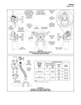
TFP964 Page 5 of 6 ROTATE TEST VALVE HOUSING AS NECESSARY FOR UNOBSTRUCTED FULL RANGE OF HANDLE OPERABILITY * TEST VALVE (NORMALLY CLOSED) TEST VALVE HOUSING (FACTORY ORIENTATION) ROTATE HANDLE 180° TO TEST FLOW * DO NOT ROTATE TEST VALVE HOUSING WHEN IN CLOSED POSITION PRESSURE RELIEF CAP SET PRESSURE MARKS OPEN POSITION DRAIN VALVE HANDWHEEL SET PRESSURE INDICATING SURFACE PRESSURE RELIEF VALVE CLOSED POSITION DRAIN VALVE (NORMALLY CLOSED) DRAIN CONNECTION SIGHT GLASS EACH SIDE FIGURE 4 MODEL TD-2 TEST AND DRAIN VALVE FEATURES AND FUNCTION MODEL RM-2 RISER MANIFOLD FLEXIBLE DRAIN HOSE...
Open the catalog to page 5
Care and Maintenance The TYCO Model RM-2 Riser Manifold must be serviced and maintained in accordance with this section. Before closing a fire protection system control valve for inspection or maintenance work on the fire protection system that it controls, obtain permission to shut down the effected fire protection system from the proper authorities and notify all personnel who may be affected by this action. The alarm/flow test procedure results in operation of the associated alarms. Notify the owner and the fire department, central station, or other signal station to which the alarms are...
Open the catalog to page 6All Tyco catalogs and technical brochures
-
Fire Protection Systems
16 Pages
-
Global protection, all togetht
12 Pages


