Model PRV-1A Pressure Reducing Valve Pilot Operated
1 /14Pages

Model PRV-1A Pressure Reducing Valve Pilot Operated
1 /14Pages
Catalog excerpts

Worldwide www.tyco-fire.com Contacts Model PRV-1A Pressure Reducing Valve Pilot Operated General Description The TYCO Model PRV-1A Pressure Reducing Valves, 2 in. to 8 in. (DN50 to DN200), are factory-assembled and fully trimmed valve arrangements for pressure control. They are used on water filled pipes, where it is necessary to reduce a higher inlet pressure to a lower delivery pressure under static and/or residual flowing conditions. The Model PRV-1A Valve is intended to automatically maintain the outlet "set pressure" (static and residual) within a close range, regardless of fluctuations in the higher pressure inlet line or varying flow rates. The Model PRV-1A Valve is provided with a factory outlet “set pressure” of approximately 125 psi (8,6 bar); however, it may be field set to a nominal outlet “set pressure” of 90 to 175 psi (6,2 to 12,1 bar). Typical applications • Within the main header, as shown in Figure 1, supplying wet pipe, dry pipe, deluge, or preaction system risers, and/or a standpipe system supplying hose connections • As part of a sectional floor control assembly, as shown in Figure 2, supplying sprinkler systems, and/or hose stations Features • Eliminates any required bleeding of trapped air from the diaphragm chamber during installation • Accurate pressure control • Epoxy coated internal and external • One piece, one moving par t diaphragm • In-line service • One pilot valve sub-assembly provides for any outlet “set pressure”, that is, 90 to 175 psi (6,2 to 12,1 bar) NOTICE The TYCO Model PRV-1A Pressure Reducing Valves described herein must be installed and maintained in compliance with this document and with the applicable standards of the NATIONAL FIRE PROTECTION ASSOCIATION (NFPA), in addition to the standards of any authorities having jurisdiction. Failure to do so may impair the performance of these devices. Owners are responsible for maintaining their fire protection system and devices in proper operating condition. Contact the installing contractor or sprinkler manufacturer with any questions. Due to the flow regulating characteristic of this device, its impact on system hydraulics should be carefully considered, especially when retrofitted into existing systems. Available End Connections Nominal Valve Size in. (DN) Flange x Flange (ANSI) NOTES: 1. EMEA and APAC only. IMPORTANT Refer to Technical Data Sheet TFP2300 for warnings pertaining to regulatory and health
Open the catalog to page 1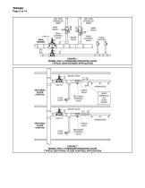
TFP1581 Page 2 of 14 WET PIPE SPRINKLER RISER DRY PIPE SPRINKLER RISER MAIN DRAIN MAIN CONTROL VALVE MAIN DRAIN MAIN CONTROL VALVE RELIEF VALVE HOSE STATIONS FIGURE 1 MODEL PRV-1A PRESSURE REDUCING VALVE TYPICAL MAIN HEADER APPLICATION RELIEF VALVE PRV-1A SECTIONAL FLOOR CONTROL SPRINKLERS CHECK VALVE HOSE VALVE SECTIONAL CONTROL VALVE RISER MANIFOLD OR ZONE CHECK RELIEF VALVE Z PRV-1A SECTIONAL FLOOR CONTROL SPRINKLERS CHECK VALVE HOSE VALVE SECTIONAL CONTROL VALVE FIGURE 2 MODEL PRV-1A PRESSURE REDUCING VALVE TYPICAL SECTIONAL FLOOR CONTROL APPLICATION
Open the catalog to page 2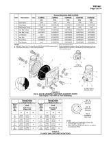
Nominal Valve Size ANSI Inch (DN) Item Valve Body Diaphragm Cover Lift Washer Hoist Ring Flat Washer NOTES: c. N/R = Not Replaceable a. Hex Bolt, Short, Qty. 6 in 6 and 8 inch (DN150 and DN200) assemblies d. Order replacements parts only via Part Numbers given, do not b. Lift Washer not used in 2 inch (DN50) assembly replace Hex Bolt, Hex Nut, Lift Washer or Hoist Ring with common hardware parts 2 INCH VALVE ONLY 6 AND 8 INCH VALVES ONLY FIGURE 3 DV-5A VALVE ASSEMBLY AND REPLACEMENT PARTS (See Figure 7 For PRV-1A Trim Assembly) Flange Drilling Specification Nominal Nominal Dimensions in. Valve...
Open the catalog to page 3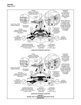
TFP1581 Page 4 of 14 WATER SUPPLY THROUGH RESTRICTION ORIFICE (NEAR SIDE PORT) PRESSURE SENSING (FAR SIDE PORT) TO AND FROM PRV-1A VALVE DOWNSTREAM PORT LOWER ADJUSTED SPRING TENSION MORE FREQUENT CYCLING OF SEAL ASSEMBLY DUE TO LOWER SPRING TENSION MAINTAINS LOWER PRESSURE IN PRV-1A VALVE CONTINUOUS DIAPHRAGM PRESSURE CHAMBER ADJUSTMENT TO DIAPHRAGM CHAMBER DIAPHRAGM CHAMBER LESSER FORCE ON DIAPHRAGM INCREASES PRV-1A VALVE WATERWAY LOWER SET REDUCED PRESSURE WATERFLOW SUPPLY PRESSURE WATERFLOW DOWNSTREAM PORT ADJUSTED PRESSURE WATERFLOW TO AND FROM P1 PILOT VALVE LESSER RESTRICTION OF PRV-1A...
Open the catalog to page 4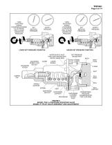
TURN ADJUSTING SCREW COUNTERCLOCKWISE TO DECREASE PRV-1A VALVE WATERFLOW PRESSURE TURN ADJUSTING SCREW CLOCKWISE TO INCREASE PRV-1A VALVE WATERFLOW PRESSURE SUPPLY PRESSURE LOWER SET PRESSURE CONDITION ADJUSTING SCREW SUPPLY PRESSURE HIGHER SET PRESSURE CONDITION WATER SUPPLY INLET PORT WITH RESTRICTION ORIFICE (NEAR SIDE) ADJUSTING SCREW LOCK HEX NUT SET PRESSURE GAUGE PORT BODY BODY PLUG COVER SCREW O-RING SEAT SEAL BODY SEAL SPRING SUPPORT SPRING DIAPHRAGM HEX NUT SEAL SUPPORT VENT DIAPHRAGM SUPPORT DIAPHRAGM CHAMBER OUTLET DIAPHRAGM PORT FIGURE 5 MODEL PRV-1A PRESSURE REDUCING VALVE MODEL...
Open the catalog to page 5
TFP1581 Page 6 of 14 DIMENSIONS SHOWN ARE APPLICABLE TO ALL END CONNECTION CONFIGURATIONS AVAILABLE PER VALVE SIZE Technical Data Approvals UL and C-UL Listed (2 in. to 6 in. only) FM Approved The UL Listing is based on the following factors: • Installation requirements referenced in the Standard for Installation of Sprinkler Systems, NFPA 13, or the Standard for Installation of Standpipe and Hose Valves, NFPA 14, as applicable. • Inspection, testing, and maintenance requirements referenced in the Standard for Inspection, Testing, and Maintenance of Water-Based Fire Protection Systems, NFPA 25....
Open the catalog to page 6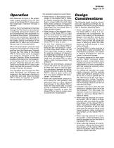
Operation With reference to Figure 4, the system water supply pressure from the inlet cavity of the Model PRV-1A Valve enters the Diaphragm Chamber through a Strainer. Exit flow from the Diaphragm Chamber through the Pilot Valve is controlled by a regulating spring that is factory set, and subsequently field adjustable, to the desired downstream “set pressure” that is to be maintained. A sensing line connects the outlet of the Pilot Valve to the system piping downstream of the Model PRV-1A Valve via the Pressure Sensor Insert in the outlet cavity. When the downstream pressure rises above the...
Open the catalog to page 7All Tyco catalogs and technical brochures
 Fire Protection Systems
16 Pages
 Global protection, all togetht
12 Pages


