


Model PRV-1A Pressure Reducing Valve Pilot Operated
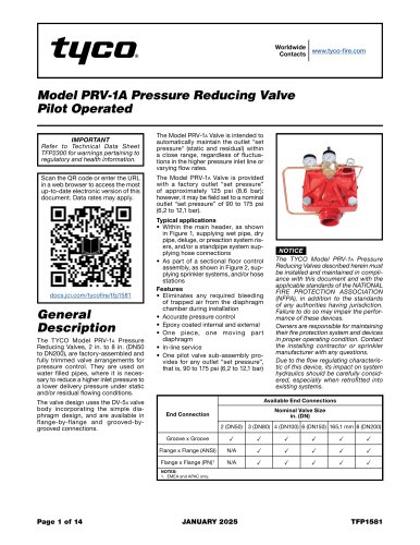
Model PRV-1A Pressure Reducing Valve Pilot Operated
The TYCO Model PRV-1A Pressure Reducing Valves are designed to control pressure in water-filled pipes, reducing higher inlet pressure to a lower delivery pressure. Available in sizes from 2 to 8 inches, they feature a diaphragm design with flange-by-flange and grooved-by-grooved connections.
Installation and maintenance must adhere to the document and NFPA standards. The valve automatically maintains outlet pressure within a close range, regardless of inlet pressure fluctuations. Owners are responsible for maintaining their fire protection systems.
These valves are typically used in main headers supplying various sprinkler systems and sectional floor control assemblies.
The valve offers accurate pressure control, epoxy coating, and a simple diaphragm design. It allows for in-line service and includes a pilot valve sub-assembly for adjustable outlet pressure.
The valve is UL and C-UL listed (2 to 6 inches) and FM approved. It has a factory outlet set pressure of 125 psi, adjustable between 90 to 175 psi. Maximum inlet pressure varies by size, with a rated flowing range specified for each size.
The valve operates by regulating flow through a pilot valve, adjusting pressure in the diaphragm chamber to maintain desired downstream pressure. The operation involves opening and closing the valve based on flow demand and pressure settings.
Considerations include positioning for gauge visibility, accessibility for maintenance, and ensuring compatibility with water conditions. The pressure differential must meet specific requirements for accuracy control.
The document specifies the use of Model PRV-1A Valves for pressure reduction in sprinkler systems, requiring a pressure relief valve downstream set 10 psi lower than the lowest rated component. An indicating valve is required on the inlet side, and provisions for a flow test must be made.
The valve can be installed in any orientation, ensuring gauges are readable and the valve is inspectable per NFPA 25. Protection from corrosion is advised, especially in outdoor or chemically exposed environments. The flow arrow on the Diaphragm Cover must align with the intended flow direction. Pipe lines should be flushed before installation, and care must be taken not to damage the trim.
Only experienced personnel should adjust downstream pressure. A flow test valve simulates system demand, requiring at least 50 gpm for smaller valves and 100 gpm for larger ones. The process involves opening and closing valves to fill the system and adjusting the Pilot Valve for desired pressure.
Regular inspection, testing, and maintenance are required per NFPA standards. The diaphragm should be replaced every five years, and flow tests are necessary to ensure proper pressure settings. Detailed steps for diaphragm and Pilot Valve replacement are provided, emphasizing correct reassembly and torque specifications.
Figures 7, 8, and 9 provide visual guidance on valve trim assembly and installation dimensions. Tables list component specifications, nominal valve sizes, and torque requirements for installation.
Specifications for diaphragm cover bolts and pressure reducing valves (PRV-1A) of various sizes, including 2, 3, 4, 6, and 8 inches, are provided. Details on minimum torque requirements and pressure drop characteristics for different valve sizes are included.
The document outlines the ordering procedure for pressure reducing valves and pressure relief valves, specifying necessary details such as valve size, outlet set pressure, and connection type for different regions.
Pressure reducing valves are designed to meet standards including ANSI B16-1 (Class 125) and ISO 7005-2 (PN16) for flange drilling specifications. References to trademarks like NFPA, CLA-VAL, and TEFLON are included.
For ordering, it is recommended to specify the valve size, outlet set pressure, and connection type. For flanged valves, the flange drilling specification must be identified.
Graphs (A to E) illustrate the minimum pressure drop for PRV-1A pressure reducing valves of different sizes, showing the relationship between flow rate in gallons per minute (GPM) and nominal pressure drop in pounds per square inch (PSI).
Maximum rate pressure for certain configurations is 250 psi (17.2 bar). Part numbers for ordering specific valve configurations and replacement parts are provided.
Catalog excerpts
Worldwide Contacts www.tyco-fire.com Model PRV-1A Pressure Reducing Valve Pilot Operated Refer to Technical Data Sheet TFP2300 for warnings pertaining to regulatory and health information. Scan the QR code or enter the URL in a web browser to access the most up-to-date electronic version of this document. Data rates may apply. The TYCO Model PRV-1a Pressure Reducing Valves, 2 in. to 8 in. (DN50 to DN200), are factory-assembled and fully trimmed valve arrangements for pressure control. They are used on water filled pipes, where it is necessary to reduce a higher inlet pressure to a lower delivery pressure under static and/or residual flowing conditions. The valve design uses the DV-5a valve body incorporating the simple diaphragm design, and are available in flange-by-flange and grooved-by-grooved connections. The Model PRV-1a Valve is intended to automatically maintain the outlet "set pressure" (static and residual) within a close range, regardless of fluctuations in the higher pressure inlet line or varying flow rates. The Model PRV-1a Valve is provided with a factory outlet “set pressure” of approximately 125 psi (8,6 bar); however, it may be field set to a nominal outlet “set pressure” of 90 to 175 psi (6,2 to 12,1 bar). Typical applications • Within the main header, as shown in Figure 1, supplying wet pipe, dry pipe, deluge, or preaction system risers, and/or a standpipe system supplying hose connections • As part of a sectional floor control assembly, as shown in Figure 2, supplying sprinkler systems, and/or hose stations • Eliminates any required bleeding of trapped air from the diaphragm chamber during installation • Accurate pressure control • Epoxy coated internal and external • One piece, one moving part diaphragm • In-line service • One pilot valve sub-assembly provides for any outlet “set pressure”, that is, 90 to 175 psi (6,2 to 12,1 bar) The TYCO Model PRV-1a Pressure Reducing Valves described herein must be installed and maintained in compliance with this document and with the applicable standards of the NATIONAL FIRE PROTECTION ASSOCIATION (NFPA), in addition to the standards of any authorities having jurisdiction. Failure to do so may impair the performance of these devices. Owners are responsible for maintaining their fire protection system and devices in proper operating condition. Contact the installing contractor or sprinkler manufacturer with any questions. Due to the flow regulating characteristic of this device, its impact on system hydraulics should be carefully considered, especially when retrofitted into existing systems.
Open the catalog to page 1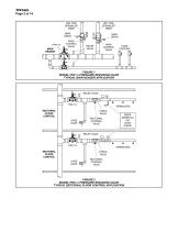
TFP1581 Page 2 of 14 WET PIPE SPRINKLER RISER DRY PIPE SPRINKLER RISER MAIN DRAIN MAIN CONTROL VALVE MAIN DRAIN MAIN CONTROL VALVE RELIEF VALVE HOSE STATIONS FIGURE 1 MODEL PRV-1A PRESSURE REDUCING VALVE TYPICAL MAIN HEADER APPLICATION RELIEF VALVE PRV-1A SECTIONAL FLOOR CONTROL SPRINKLERS CHECK VALVE HOSE VALVE SECTIONAL CONTROL VALVE RISER MANIFOLD OR ZONE CHECK RELIEF VALVE Z PRV-1A SECTIONAL FLOOR CONTROL SPRINKLERS CHECK VALVE HOSE VALVE SECTIONAL CONTROL VALVE FIGURE 2 MODEL PRV-1A PRESSURE REDUCING VALVE TYPICAL SECTIONAL FLOOR CONTROL APPLICATION
Open the catalog to page 2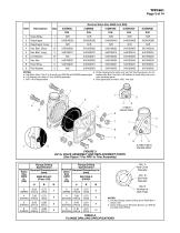
NOTES: d. Order replacements parts only via Part Numbers given, do not a. Hex Bolt, Short, Qty. 6 in 6 and 8 inch (DN150 and DN200) assemblies replace Hex Bolt, Hex Nut, Lift Washer or Hoist Ring with comb. Lift Washer not used in 2 inch (DN50) assembly mon hardware parts c. N/R = Not Replaceable e. Also applicable to metric 165,1 mm size. Dim. A Bolt Circle Diameter Dim. B Bolt Hole Diameter Qty. N Number of Bolt Holes a. Flat face flange; Same drilling as for ANSI B16.1 (Class 125) b. Same drilling as for BS 4504 Section 3.2 (PN16) and DIN 2532 (PN16)
Open the catalog to page 3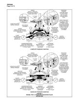
TFP1581 Page 4 of 14 WATER SUPPLY THROUGH RESTRICTION ORIFICE (NEAR SIDE PORT) PRESSURE SENSING (FAR SIDE PORT) TO AND FROM PRV-1A VALVE DOWNSTREAM PORT LOWER ADJUSTED SPRING TENSION MORE FREQUENT CYCLING OF SEAL ASSEMBLY DUE TO LOWER SPRING TENSION MAINTAINS LOWER PRESSURE IN PRV-1A VALVE CONTINUOUS DIAPHRAGM PRESSURE CHAMBER ADJUSTMENT TO DIAPHRAGM CHAMBER DIAPHRAGM CHAMBER LESSER FORCE ON DIAPHRAGM INCREASES PRV-1A VALVE WATERWAY LOWER SET REDUCED PRESSURE WATERFLOW SUPPLY PRESSURE WATERFLOW DOWNSTREAM PORT ADJUSTED PRESSURE WATERFLOW TO AND FROM P1 PILOT VALVE LESSER RESTRICTION OF PRV-1A...
Open the catalog to page 4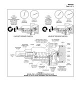
TURN ADJUSTING SCREW COUNTERCLOCKWISE TO DECREASE PRV-1A VALVE WATERFLOW PRESSURE TURN ADJUSTING SCREW CLOCKWISE TO INCREASE PRV-1A VALVE WATERFLOW PRESSURE SUPPLY PRESSURE LOWER SET PRESSURE CONDITION ADJUSTING SCREW SUPPLY PRESSURE HIGHER SET PRESSURE CONDITION WATER SUPPLY INLET PORT WITH RESTRICTION ORIFICE (NEAR SIDE) ADJUSTING SCREW LOCK HEX NUT SET PRESSURE GAUGE PORT BODY BODY PLUG COVER SCREW O-RING SEAT SEAL BODY SEAL SPRING SUPPORT SPRING DIAPHRAGM HEX NUT SEAL SUPPORT VENT DIAPHRAGM SUPPORT DIAPHRAGM CHAMBER OUTLET DIAPHRAGM PORT FIGURE 5 MODEL PRV-1A PRESSURE REDUCING VALVE MODEL...
Open the catalog to page 5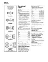
Pressure Loss with Inlet Pressure Below “Set Pressure” See Graphs A to E. These graphs are a requirement of UL and should be used as reference only. Rated Flowing Range TechnicalData Approvals UL and C-UL Listed (2 in. to 6 in. only) FM Approved The UL Listing is based on the following factors: • Installation requirements referenced in the Standard for Installation of Sprinkler Systems, NFPA 13, or the Standard for Installation of Standpipe and Hose Valves, NFPA 14, as applicable. • Inspection, testing, and maintenance requirements referenced in the Standard for Inspection, Testing, and Maintenance...
Open the catalog to page 6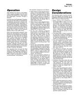
With reference to Figure 4, the system water supply pressure from the inlet cavity of the Model PRV-1a Valve enters the Diaphragm Chamber through a Strainer. Exit flow from the Diaphragm Chamber through the Pilot Valve is controlled by a regulating spring that is factory set, and subsequently field adjustable, to the desired downstream “set pressure” that is to be maintained. A sensing line connects the outlet of the Pilot Valve to the system piping downstream of the Model PRV-1a Valve via the Pressure Sensor Insert in the outlet cavity. When the downstream pressure rises above the “set pressure”...
Open the catalog to page 7All Tyco catalogs and technical brochures
 Fire Protection Systems
16 Pages
Archived catalogs
 Global protection, all togetht
12 Pages

