


Model BFV-300/BFV-300C Butterfly Valve Grooved End
Model BFV-300/BFV-300C Butterfly Valve Grooved End
The document details the TYCO Model PRV-1 Pressure Reducing Valve, a pilot-operated valve available in globe and angle body styles, designed for fire protection systems to reduce higher inlet pressures to lower outlet pressures.
- Sizes: 2 to 8 inches (DN50 to DN200).
- Outlet pressure range: 80 to 225 psi (5.5 to 15.5 bar) per FM Approval, 80 to 150 psi (5.5 to 10.3 bar) per UL Listing.
- Maximum inlet pressure: 250 psi (17.2 bar).
- UL and C-UL Listed, FM Approved.
- One-piece diaphragm with one moving part.
- In-line service capability.
- Installable in vertical or horizontal orientations.
- RILSAN Red coated for corrosion resistance.
- Suitable for main headers in fire protection systems like wet pipe, dry pipe, deluge, or preaction systems.
- Can be part of a sectional floor control assembly for sprinkler systems and hose stations.
- Must comply with NFPA standards and local regulations.
- Owners must maintain the valve in proper condition.
- Factory-set needle valve adjustment should not be altered.
The valve regulates flow through a pilot valve, adjusting diaphragm chamber pressure to maintain desired downstream pressure, opening and closing based on flow demand and pressure settings.
- Install in accessible locations, protected from freezing and damage.
- Designed for fresh water service; may need additional protection in corrosive environments.
- Body and diaphragm cover: Ductile iron with RILSAN polyamide 11 coating.
- Diaphragm: Nylon fabric-reinforced natural rubber.
- Other components: Brass, stainless steel, copper.
- End connections: Threaded, grooved, flanged.
- Configurations for North America and international standards.
- Illustrate typical applications and valve assembly.
- Provide details on sizes, configurations, and dimensional specifications for flange drilling.
- Emphasizes owner's responsibility for compatibility with components.
- Minimum pressure differential: 25 psi (1.7 bar) for FM Approval, 50 psi (3.4 bar) for UL Listing.
- Cavitation risks noted; recommends two-step pressure reduction using two valves in series.
- Align flow arrow on Diaphragm Cover with intended flow direction.
- Flush pipelines before installation; avoid lifting valve by trim.
- Alterations to trim discouraged.
- 13-step procedure for service placement, including pressure adjustments by experienced personnel.
- Importance of simulating system demand during setup and maintaining pressure setting records.
- Comply with NFPA standards; correct system impairments immediately.
- Avoid field repairs of Pilot Valve; replace diaphragm every five years.
- Strainer maintenance involves disassembly and cleaning.
- Required every five years to compare outlet pressure with previous tests.
- Guidance provided for readjusting valve settings if needed.
- Instructions for replacement include taking valve out of service and ensuring proper reinstallation.
- Torque specifications provided for diaphragm cover bolts.
- Tables provide dimensions and weights for various valve sizes and connection types.
- Illustrate outlet pressure versus flow rate for different inlet pressures, serving as a reference for system performance.
Technical specifications and ordering information for PRV-1 models, including graphs for outlet pressure and flow rate relationships, and detailed ordering procedures and part numbers.
- Specify valve type, size, outlet set pressure, connection type, and part number.
- Part numbers provided for each configuration.
- Pressure Relief Valve: 1/2 inch (DN15) Watts Regulator, Series 530C.
- Replacement Parts: Specify description and size for Model PRV-1.
Refer to the manufacturer's website for warranty terms and conditions.
Catalog excerpts
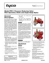
Worldwide Contacts www.tyco-fire.com Model PRV-1 Pressure Reducing Valve Pilot Operated, Globe and Angle Body Styles Refer to Technical Data Sheet TFP2300 for warnings pertaining to regulatory and health information. The TYCO Model PRV-1 Pressure Reducing Valves, 2 through 8 in. (DN50 through DN200), are factory-assembled and fully trimmed valve arrangements for pressure control. They are used on water filled pipe where it is necessary to reduce a higher inlet pressure to a lower delivery pressure under static and/or residual flowing conditions. The Model PRV-1 Valve is intended to automatically maintain the outlet "set pressure" (static and residual) within a close range, regardless of fluctuations in the higher pressure inlet line or varying flow rates. The Model PRV-1 Valve is provided with a factory outlet “set pressure” of 125 psi (8,6 bar); however, it may be field set to a nominal outlet “set pressure” of 80 to 225 psi (5,5 to 15,5 bar) per its FM Approval or 80 to 150 psi (5,5 to 10,3 bar) per its UL Listing. Typical applications • Within the main header (Ref. Figure 1) supplying wet pipe, dry pipe, deluge, or preaction system risers, and/or a standpipe system supplying hose connections • As part of a sectional floor control assembly (Ref. Figure 2) supplying sprinkler systems, and/or hose stations • Can be installed in vertical or horizontal orientation • Eliminates any required bleeding of trapped air from the diaphragm chamber during installation • Globe or angle pattern • Accurate pressure control • RILSAN Red coated internal and external • One piece, one moving part diaphragm • In-line service • One pilot valve sub-assembly provides for any outlet “set pressure”, that is, 80 to 225 psi (5,5 to 15,5 bar) The TYCO Model PRV-1 Pressure Reducing Valves described herein must be installed and maintained in compliance with this document and with the applicable standards of the National Fire Protection Association (NFPA), in addition to the standards of any authorities having jurisdiction. Failure to do so may impair the performance of these devices. Owners are responsible for maintaining their fire protection system and devices in proper operating condition. Contact the installing contractor or sprinkler manufacturer with any questions. Due to the flow regulating characteristic of this device, its impact on system hydraulics should be carefully considered, especially when retrofitted into existing systems. Adjustment of the Needle Valve is factory set and must not be altered. • Installation requirements referenced in the Standard for Installation of Sprinkler Systems, NFPA 13, or the Standard for Installation of Standpipe and Hose Valves, NFPA 14, as applicable. • Inspection, testing, and maintenance requirements referenced in the Standard for Inspection, Testing, and Maintenance of Water-Based Fire Protection Systems, NFPA 25. • Testing of the Model PRV-1 Valve after installation in accordance with NFPA 13 and/or NFPA 14 as applicable. • Testing the Model PRV-1 Valve tested periodically thereafter in accordance with NFPA 25. Factory Outlet “Set Pressure” Field Outlet “Set Pressure” Range 80 to 225 psi (5,5 to 15,5 bar) per FM Approval, or 80 to 150 psi (5,5 to 10,3 bar) per UL Listing Pressure Loss With Inlet Pressure Above “Set Pressure” The inlet pressure minus the outlet “set pressure” equals pressure loss. For
Open the catalog to page 1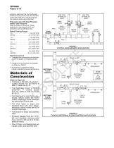
TFP1580 Page 2 of 16 example, assuming that the inlet flowing pressure is 225 psi (15,5 bar) and the field outlet “set pressure” is 130 psi (9,0 bar), the pressure loss is 95 psi (6,5 bar). WET PIPE SPRINKLER RISER MAIN DRAIN Pressure Loss with Inlet Pressure Below “Set Pressure” Refer to Graphs A through E. These graphs are a requirement of UL and should be used as reference only. Rated Flowing Range DRY PIPE SPRINKLER RISER MAIN DRAIN MAIN CONTROL VALVE MAIN CONTROL VALVE RELIEF VALVE HOSE STATIONS FIGURE 1 TYPICAL MAIN HEADER APPLICATION • Threaded end connections are available as NPT threaded...
Open the catalog to page 2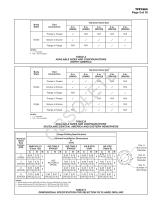
a. Same drilling as for ANSI B16.5 (Class 150) and ANSI B16.42 (Class 150) b. Same drilling as for BS 4504 Section 3.2 (PN10) and DIN 2532 (PN10) c. Same drilling as for BS 4504 Section 3.2 (PN16) and DIN 2532 (PN16) Dim. A Bolt Circle Diameter Dim. B Bolt Hole Diameter Qty. N Number of Bolt Holes DIMENSIONAL SPECI
Open the catalog to page 3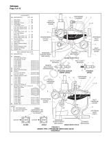
VALVE PARTS QTY. KIT NO. DESCRIPTION DOWNSTREAM OUTLET CAVITY UPSTREAM INLET CAVITY 8 Diaphragm, Fits Either Body Style, Includes Item 2 only: 2 Inch Valves . . . . . . . . . . . . . 92-570-2-011 3 Inch Valves . . . . . . . . . . . . . 92-570-2-012 4 Inch Valves . . . . . . . . . . . . . 92-570-2-013 6 Inch Valves . . . . . . . . . . . . . 92-570-2-014 8 Inch Valves . . . . . . . . . . . . . 92-570-2-015 Pilot Valve . . . . . . . . . . . . . . . 92-570-2-200 Water Pressure Gauge . . . . . 92-570-2-211 Strainer: 2, 3, & 4 Inch Valves . . . . . . . 92-570-2-202 6 & 8 Inch Valves . . . . . . . ....
Open the catalog to page 4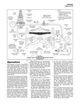
PILOT VALVE ADJUSTING SCREW OUTLET PRESSURE GAUGE NEEDLE VALVE (FACTORY SET, DO NOT READJUST) LOCKNUT REGULATING SPRING COMPRESSION FITTING EXIT FLOW NOTES: 1. SOME PARTS SHOWN IN ALTERED POSITIONS AND ORIENTATIONS TO CLARIFY FUNCTION 2. ELBOW AND TEE FITTINGS VARY BY VALVE SIZE AND BODY TYPE SUPPLY LINE DIAPHRAGM CHAMBER COMPRESSION FITTING PILOT VALVE DIAPHRAGM VALVE BODY OUTLET CAVITY INTERIOR INLET PRESSURE GAUGE PRESSURE SENSOR INSERT DOWNSTREAM OUTLET CAVITY SENSING LINE SENSING LINE PILOT VALVE SEAT PRESSURE SENSOR INSERT (INLET FACES DOWNSTREAM) SYSTEM WATER SUPPLY PRESSURE UPSTREAM INLET...
Open the catalog to page 5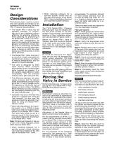
The following items must be considered and applied accordingly for an installation that will be using the Model PRV-1 Pressure Reducing Valve: • The Model PRV-1 Valve may be installed vertically or horizontally and in any orientation without affecting its operating efficiency. When planning the positioning of the Model PRV-1 Valve, it is recommended that consideration be given to the viewing of the pressure gauges. Consideration should also be given to positioning the Model PRV-1 Valve so that the diaphragm cover is facing up. With the cover facing up, internal access is more easily achieved....
Open the catalog to page 6All Tyco catalogs and technical brochures
 Fire Protection Systems
16 Pages
Archived catalogs
 Global protection, all togetht
12 Pages

