- Catalogs
- TYCO FIRE & INTEGRATED SOLUTION
- Model BFV-300/BFV-300C Butterfly Valve Grooved End
Model BFV-300/BFV-300C Butterfly Valve Grooved End
1 /8Pages
Model BFV-300/BFV-300C Butterfly Valve Grooved End
1 /8Pages
Catalog excerpts

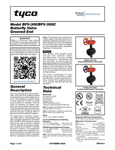
Worldwide www.tyco-fire.com Contacts Model BFV-300/BFV-300C Butterfly Valve Grooved End IMPORTANT Refer to Technical Data Sheet TFP2300 for warnings pertaining to regulatory and health information. Scan the QR code or enter the URL in a web browser to access the most up-to-date electronic version of this document. Data rates may apply. General Description The TYCO Models BFV-300 and BFV300C Grooved End Butterfly Valves are indicating type valves designed for use in fire protection systems where a visual indication of open or closed valve condition is required. They are used, for example, as system, sectional and pump water control valves. They have grooved inlet and outlet connections that are suitable for use with grooved end pipe couplings listed or approved for fire protection systems. For applications requiring supervision of the open or closed state of the valve, the gear operators for the Model BFV-300/BFV-300C Butterfly Valves feature two sets of factory installed internal switches each having singlepole double-throw (SPDT) contacts as shown in Figure 3. The supervisory switches transfer their electrical contacts when there is movement from the open or closed disc position during the first two revolutions of the handwheel. Note: If the butterfly valve is required in a foam system, verify the valve is compatible by referring to the foam concentrate manufacturer technical literature for information about foam compatibility, and acceptable system equipment materials of construction. NOTICE The Model BFV-300/BFV-300C Grooved End Butter fly Valves described herein must be installed and maintained in compliance with this document, as well as with the applicable standards of the NATIONAL FIRE PROTECTION ASSOCIATION, in addition to the standards of any other authorities having jurisdiction. Failure to do so may impair the performance of these devices. MODEL BFV-300 OPEN SUPERVISORY SWITCHES The owner is responsible for maintaining their fire protection system and devices in proper operating condition. Contact the installing contractor or product manufacturer with any questions. Technical Data MODEL BFV-300C CLOSED SUPERVISORY SWITCHES UL and ULC Listed FM Approved CE Certified VdS Approved CNPP Certified 63.23.221 Listed by California State Fire Marshall Note: For specific information about approvals, see Tables A, B, and C. Note: All laboratory listings and approvals are for indoor and outdoor use. UL/ULC/FM Maximum Working Pressure VdS Maximum Working Pressure Note: The permissible flow velocity in relation to the nominal cross-section (at least 6 m/s). Maximum Working Temperature Body ��������������������������������������������������Ductile Iron Body Coating ���������������������� RILSAN PA11 Black Disc ����������������������������������������������������Ductile Iron Disc Seal. . . . . . . . . . . . . . . EPDM Encapsulated Upper & Lower Stem �������������������� Stainless Steel Handwh
Open the catalog to page 1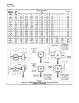
TRAVELLING NUT GEAR OPERATOR 2 TO 4 INCH (DN50 TO DN100) VALVE SIZES SEGMENTED GEAR OPERATOR 8 TO 12 INCH (DN200 TO DN300) VALVE SIZES TRAVELLING NUT GEAR OPERATOR 5 TO 6 INCH (DN125 TO DN150) VALVE SIZES Nominal Valve Size in. (DN)
Open the catalog to page 2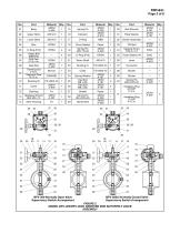
BFV-300 Normally Open Valve Supervisory Switch Arrangement BFV-300C Normally Closed Valve Supervisory Switch Arrangement
Open the catalog to page 3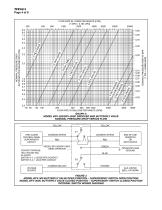
FLOW RATE IN LITERS PER MINUTE (LPM) (1 GPM = 3,785 LPM) 1000 2000 4000 6000 NOMINAL PRESSURE DROP IN BAR (1 PSI = 0,06895 BAR) NOMINAL PRESSURE DROP IN POUNDS PER SQUARE INCH (PSI) 200 400 600 800 1000 FLOW RATE IN GALLONS PER MINUTE (GPM) GRAPH A MODEL BFV-300/BFV-300C GROOVED END BUTTERFLY VALVE NOMINAL PRESSURE DROP VERSUS FLOW YELLOW FIRE ALARM CONTROL PANEL SUPERVISORY CIRCUIT COMMON (WHITE) COMMON (WHITE) MODEL BFV-300/BFV-300C GEAR OPERATOR CONTACT RATINGS: 16A 125V/250 VAC 5A 24VDC SWITCH S-1, 2 LEADS PER CONTACT SWITCH S-2, 1 LEAD PER CONTACT VOLTAGE SOURCE COMMON (BLACK) END OF LINE...
Open the catalog to page 4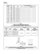
1. Install a single switch in either bracket mounting position to monitor Open or Closed valve condition Bernstein Switch Wiring Diagram MODEL BFV-300 GROOVED END BUTTERFLY VALVE WITHOUT INTERNAL SUPERVISORY SWITCHES ACCESSORY EXTERNAL SUPERVISORY SWITCHES AND MOUNTING BRACKETS
Open the catalog to page 6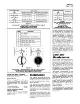
BFV-300/BFV-300C GROOVED END BUTTERFLY VALVE SEGMENTED GEAR OPERATOR ADJUSTMENT (8 IN. (DN200) AND LARGER VALVES ONLY) Silicone Free Model Availability Silicone free models are available. Contact TYCO sales for information. Tapping Bosses Two factory-plugged NPT threaded tapping bosses in the valve body are located on the up- and downstream sides of the disc for connection to valve trim. Tapping boss sizes: Control Valve Seat Leakage Class IEC60534-4 CLASS VI (Type C) Control Valve Seat Leakage according to ANSI/FCI 70-2-2006 (ASME B16.104) The Model BFV-300/BFV-300C Grooved End Butterfly Valves...
Open the catalog to page 7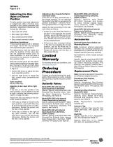
The disc position may need adjustment or realignment while in the disc open (parallel) or disc closed (perpendicular) positions. Adjustment scenarios may include the following: • Disc open left offset • Disc open right offset • Disc closed shortfall offset • Disc closed overreach offset Adjustment guidelines: This procedure applies to 8 in. (DN200) and larger valves that are equipped with segmented gear operators. The adjustments must be made only while the position of the valve disc can be observed —either prior to valve installation, or when the valve is removed for the purpose of adjusting...
Open the catalog to page 8All TYCO FIRE & INTEGRATED SOLUTION catalogs and technical brochures
 RTP 3000 SIS
2 Pages
 Firewater De-scaling System
2 Pages

Archived catalogs
 Chemical Injection Systems
2 Pages
 Wellhead, Process & Control
6 Pages


- Bourn And Koch piping
- Bourn And Koch fitting
- Bourn And Koch manual valve
- Bourn And Koch hydraulic fitting
- Water valve
- Bourn And Koch metal fitting
- Regulating valve
- Flange valve
- On/off valve
- Bourn And Koch quick coupling
- Flap valve
- Check valve
- Bourn And Koch structure hose
- Bourn And Koch lever valve
- Nickel-plated brass fitting
- Floor-mounted cabinet