- Catalogs
- TWK-ELEKTRONIK GmbH
- Vibration sensor NVA
- Company
- Products
- Catalogs
- News & Trends
- Exhibitions
Vibration sensor NVA
1 /12Pages

Vibration sensor NVA
1 /12Pages
Catalog excerpts
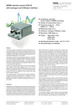
MEMS vibration sensor NVA 65 with analogue and CANopen interface Design The sensor system is intended as a component for use e.g. in wind power plants to measure and evaluate vibrations in the mast head. Registration of dynamic accelerations by means of MEMS sensors (Micro-Electro-Mechanical System) with subsequent digitisation by a controller. The device consists of an acceleration sensors, a controller unit and three types of output interface. Data output is carried out via two analogue interfaces with 4 ... 20 mA plus CANopen and via 4 relay contacts (currently 1 error relay contact). The NVA is parameterised via the CANopen interface. This is not galvanically separated. The sensor is equipped with a filter circuit to protect against fast transients and surge voltages of up to 2 kV in the supply. The protection types are IP 69K (housing) and IP 67 (connector/socket). With its good vibration and shock values, the sensor is suitable for use in areas with rough environmental conditions. The vibration sensor is equipped with a stable aluminium housing (optionally stainless steel). Elongated holes are available for mechanical alignment (up to approx. ± 7.5°). Electrical connection is carried out using two connectors or two cables. Function MEMS sensors are integrated circuits which are manufactured in silicon bulk micromechanics technology. Double capacities are formed with the aid of these micromechanical structures. If these structures are deflected in the case of accelerations, this leads to capacity changes which are registered using measuring technology and further processed. The sensors measure precisely, have a long service life and are very robust. ■ Contactless, wear-free sensor system in MEMS technology ■ Number of measurement axes: 2 ■ Frequency range: 0.1 ... 60 Hz Option: 0.1 ... 100 Hz ■ Measuring range: ± 2 g ■ Interfaces: analogue, CANopen, relays ■ Resolution: 4096 digits / g ■ Output: Momentary value RMS value Peak value ■ Operating temperature range: - 40 °C to + 85 °C ■ Parameterisable via CANopen After determining the steady component and scaling, the measured values supplied by the acceleration sensor are made available to the six filter units. The steady component arises as a result of installation which is not precisely horizontal, with the result that part of the earth's gravitational field would also be measured. The offset which occurs in the measured vibration value curve (zero point shift) due to the steady component is determined by means of calculation (distribution of the positive and negative measured values around the zero point) and is subtracted. The pure alternating component is output within a matter of seconds. This calculation takes place continually. The filter units can be individually programmed by the customer as regards their sampling frequency, whilst their filter characteristics can be programmed in the factory. Each filter unit additionally has two outputs (flags) for alarm and warning. If the amount of a filter output's measured value exceeds the set limit value the output is activated. The limit values for triggering the outputs can also be programmed by the customer. The warning and alarm outputs can be connected to the four relay outputs via a matrix which can be programmed by the customer. Several filter outputs may additionally be connected to the relay outputs by means of an OR link. The analogue outputs are firmly connected to filters 1 and 2. The outputs output the filtered signed signal supplied by the acceleration sensor. The quiescent level of the 4 ... 20 mA interface is 12 mA with an acceleration of 0 m/s2 or 0 g. Amplifier setting is individually possible for each channel via the CANopen interface. The CANopen interface can be used to set the parameters and call up the 6 filters' outputs. With the exception of the filter characteristics, all parameters are programmable. TWK-ELEKTRONIK GmbH Heinrichstrasse 85 [email protected] www.twk.de
Open the catalog to page 1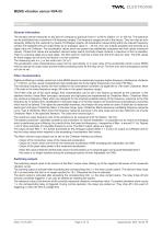
MEMS vibration sensor NVA 65 Description General information The vibration sensor measures on two axes in a frequency spectrum from 0.1 to 60 Hz (Option: 0.1 to 100 Hz). This spectrum can be subdivided into a maximum of 6 frequency ranges. The frequency ranges are set in the factory. They can also be subsequently shifted by the customer by means of CANopen objects. All acceleration values acting within the relevant frequency window are registered and are output firstly as an analogue value (4 ... 20 mA, max. two outputs possible) and secondly as a digital value via CANopen. The acceleration values...
Open the catalog to page 2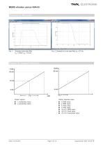
MEMS vibration sensor NVA 65 Examples for fiter output Fig. 1: Example band pass filter fgu = 0.8Hz, fgo = 2.5 Hz Fig. 2: Example of a low pass filter fgo = 23 Hz Diagram for analogue output I0(a) I [mA] Output: signed Output: absolute value x, momentary value y, momentary value x, RMS value y, RMS value x, Peak value y, Peak value √(x²+y²), RMS value √(x²+y²), Peak value √(x²+y²), momentary value
Open the catalog to page 3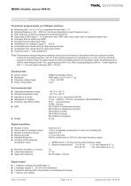
Parameters programmable via CANopen interface ■ Measuring axis: x or y or V(x2+y2) separately for each filter 1 - 6 ■ Sampling frequency (120 ... 800 Hz). Can be set separately for each frequency band. ■ Filter frequency range (by changing the sampling frequency)* ■ Signal type at filter output 1 - 6: momentary value, RMS mean value, peak value or degressive peak value ■ Averaging time for signal type 'RMS' ■ Decrease time for signal type 'Peak' ■ Amplification for analogue outputs 4 ... 20 mA ■ Acceleration limit values (limit) for relay warning function ■ Acceleration limit values (limit) for...
Open the catalog to page 4
MEMS vibration sensor NVA 65 Optional functions (subject to consultation with TWK) System calibration for higher accuracy Programmable steady component in the output signal (measured vibration value curve zero point shift) Up to 8 relays Transistors instead of relays Further filters Evaluation procedures (Datalogging, log functions with programmable triggering, statistics, protocol functions) Safety design for safety applications Other customer variants CANopen technical data CANopen communication profile Full CAN part A (11-bit) CANopen 301 V 4.1 (no galvanic bus separation)...
Open the catalog to page 5All TWK-ELEKTRONIK GmbH catalogs and technical brochures
 Rotary encoder TBN58/C3 manual
50 Pages
 Rotary encoder TBN58/C3
22 Pages
 Rotary encoder TBD Manual
26 Pages
 Rotary encoder TBD
12 Pages
 Rotary encoder TBE58
16 Pages
 Rotary encoder KRP - Manual
19 Pages
 Rotary encoder KRP
7 Pages
 Rotary encoder TBN58/S4 SIL2
22 Pages
 Rotary encoder TBN50/C3 manual
20 Pages
 Rotary encoder TBN50/C3
22 Pages
 Rotary encoder HBN/S3 SIL2
16 Pages
 Product range 2022
64 Pages
 Image brochure TWK
28 Pages
 Inclinometer NBA51
6 Pages
 Incremental encoder FOI
7 Pages
 Rotary encoder TBA42
16 Pages
 Rotary encoder TRA42
16 Pages
 Rotary encoder TRN58/S4 SIL2
22 Pages
 Rotary encoder TRN58/C3 manual
50 Pages
 Rotary encoder TRN58/C3
22 Pages
 Rotary encoder TRN42/S4 SIL2
22 Pages
 Manual TRN50/C3
86 Pages
 Rotary encoder TRN50/C3
22 Pages
 Rotary encoder TRN42/C3 manual
86 Pages
 Rotary encoder TRN42/C3
22 Pages
 Rotary encoder TBN42/S4 SIL2
22 Pages
 Rotary encoder TBN42/C3 manual
86 Pages
 Rotary encoder TBN42/C3
22 Pages
 Rotary encoder TRE58
16 Pages
 Rotary encoder TRT manual
40 Pages
 Rotary encoder TRT
14 Pages
 Switching cam encoder NOCE
14 Pages
 Switching cam encoder NOCA
17 Pages
 Vibration sensor NVT/S3 PLd
12 Pages
 Inclinometer NBN
17 Pages
 Incremental encoder TBI42
6 Pages
 Vibration sensor NVA/S3 PLd
15 Pages
 Rotary transducer PMR411
1 Page
 Rotary encoder TRT/S3 SIL2
13 Pages
 Rotary transducer VP12
1 Page
 Switching cam encoder NOCN
22 Pages
 Inclination sensor NBT manual
21 Pages
 Inclination sensor NBT
10 Pages
 Inclinometer NBA
17 Pages
 Inclinometer NBT/S3 SIL2/PLd
12 Pages
 Inclinometer NBN/S3 SIL2
13 Pages
 Rotary encoder TBE50
16 Pages
 Rotary encoder HBE
14 Pages
 Rotary encoder TRK manual
18 Pages
 Rotary encoder TRK
11 Pages
 Rotary encoder TMN50 manual
22 Pages
 Rotary encoder TMN50
6 Pages
 Rotary encoder TRK/S3 SIL2
14 Pages
 Rotary encoder TRE42
6 Pages
 Rotary encoder TRE50
6 Pages
 Rotary encoder TRA50
6 Pages
 Rotary encoder TBE42
6 Pages
 Rotary encoder TME42
6 Pages
 Rotary encoder TRD manual
26 Pages
 Rotary encoder TRD
12 Pages
 Rotary encoder TME50
6 Pages
 Rotary encoder TBN36
6 Pages
 Rotary encoder TMA50
6 Pages
 Rotary encoder TMN42 manual
22 Pages
 Rotary encoder TMN42
6 Pages
 Rotary encoder TMA42
6 Pages
 Rotary encoder TBA50
16 Pages
 Rotary encoder TBE36 manual
22 Pages
 Rotary encoder TBE36
6 Pages
 Rotary encoder TBN42
6 Pages
 Rotary encoder TBN37
8 Pages
 Rotary encoder TBA37
7 Pages
 Rotary encoder TBB50
16 Pages
 Rotary encoder PBA12
2 Pages
 Rotary encoder TBA36
6 Pages
 Rotary encoder TKA60
2 Pages
 Rotary encoder TKN46 manual
22 Pages
 Rotary encoder TKN46
7 Pages


- SARRALLE rotary encoder
- SARRALLE incremental encoder
- SARRALLE incremental rotary encoder
- SARRALLE absolute rotary encoder
- SARRALLE inclinometer
- SARRALLE magnetic rotary encoder
- Industrial rotary encoder
- Displacement transducer
- Linear displacement sensor
- SARRALLE digital inclinometer
- SARRALLE aluminum rotary encoder
- SARRALLE stainless steel rotary encoder
- SARRALLE single-turn rotary encoder
- MEMS inclination sensor
- Flange rotary encoder
- Multi-axis tilt sensor
- SARRALLE ultra-rugged rotary encoder
- SSI angular encoder
- SARRALLE multi-turn rotary encoder
- Analog displacement transducer